


1. ņä£ ļĪĀ
2. ņŗżĒŚśņ×¼ļŻī ļ░Å ņŗżĒŚśļ░®ļ▓Ģ
Table┬Ā1
| Sheets | Thickness [mm] | Tensile strength [MPa] |
|---|---|---|
| CFRP[0┬║] | 0.9 | 1131 |
| 1.3 | 995 | |
| 1.8 | 1032 | |
| GA-590 DP | 0.8 | 635 |
| 1.4 | 607 | |
| Al5052-H32 | 1.2 | 231 |


3. ņŗżĒŚśĻ▓░Ļ│╝ ļ░Å Ļ│Āņ░░
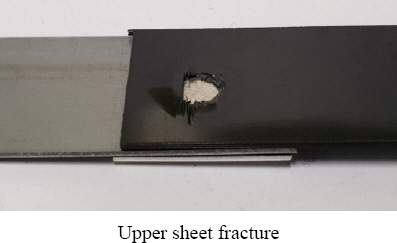
3.1 ņåīņ×¼ņł£ņä£ ņĪ░ĒĢ®ņŚÉ ļö░ļźĖ ņØĖņןĒĢśņżæ
Table┬Ā2
Fig.┬Ā7


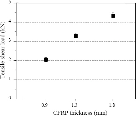
3.2 ņāüĒīÉ CFRPņØś ļæÉĻ╗śņŚÉ ļö░ļźĖ ņØĖņןĒĢśņżæ
Fig.┬Ā10

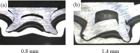
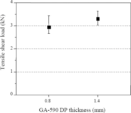
3.3 ņāüĒīÉ GA-590 DP ļæÉĻ╗śņŚÉ ļö░ļźĖ ņØĖņןĒĢśņżæ
Fig.┬Ā13
4. Ļ▓░ ļĪĀ
1) CFRPļź╝ ĒĢśĒīÉņŚÉ ņ£äņ╣śĒĢĀ Ļ▓ĮņÜ░ rivet ņ▓┤Ļ▓░ņØä ņ£äĒĢ£ ņä▒ĒśĢņä▒ņØ┤ ļČĆņĪ▒ĒĢśņŚ¼ ņĀæĒĢ®ņØ┤ ļČłĻ░ĆļŖźĒĢśņśĆļŗż.
2) ĒĢśĒīÉņØ┤ steelņØ╝ ļĢī ļæÉĻ╗śĻ░Ć 0.8 mm ņØ┤ĒĢśņØ┤ļ®┤ ĒĢśĒīÉņŚÉņä£ rivetņØ┤ ņä▒ĒśĢ Ļ░ĆļŖźĒĢ£ ļæÉĻ╗śĻ░Ć ļČĆņĪ▒ĒĢśņŚ¼ ņĀæĒĢ®ņØ┤ ļČłĻ░ĆļŖźĒĢśņśĆļŗż.
3) GA-590 DPĻ░Ć ņāüĒīÉņØĖ ņĪ░ĒĢ®ņŚÉņä£ rivetņØś ņóīĻĄ┤Ļ│╝ ļ╣äļīĆņ╣ŁņØ┤ ņØ╝ņ¢┤ļé¼ņ£╝ļ®░ ņØ┤ņŚÉ ļö░ļØ╝ ņØĖņןĒĢśņżæĻ░ÆņØĆ Ēü░ ņé░ļ×ĆļÅäļź╝ ļ│┤ņØ┤ļ»ĆļĪ£ ļČĆņĀüĒĢ®ĒĢ£ ņĪ░Ļ▒┤ņ£╝ļĪ£ ĒīÉņĀĢĒĢśņśĆņ£╝ļ®░, ņżæĒīÉņØś CFRPļź╝ rivetņØ┤ Ļ┤ĆĒåĄĒĢśņ¦Ć ļ¬╗ĒĢśņśĆļŗż.
4) CFRPļŖö SteelĻ│╝ AluminumņŚÉ ļ╣äĒĢ┤ ļåÆņØĆ ņØĖņןĻ░ĢļÅäļź╝ ļéśĒāĆļé┤ņŚłļŗż. ĻĘĖļ¤¼ļéś ļ│Ė ņŗżĒŚśņØś SPR ņĀæĒĢ® ņĪ░Ļ▒┤ņŚÉņä£ļŖö ņŻ╝ļĪ£ CFRPņØś Ēīīļŗ©ņØ┤ ļ░£ņāØĒĢśņśĆņ£╝ļ®░ ņØ┤ļź╝ ĒåĄĒĢ┤ CFRPĻ░Ć ņĘ©ņĢĮļČĆņØĖ Ļ▓āņØä ĒÖĢņØĖĒĢśņśĆļŗż. ļö░ļØ╝ņä£ CFRPņØś ļæÉĻ╗śļź╝ ņ”ØĻ░Ćņŗ£ĒéżĻ▒░ļéś CFRPņØś ļ░░ņ╣śļź╝ ņżæĒīÉņŚÉ ņ£äņ╣śņŗ£Ēé┤ņ£╝ļĪ£ņä£ ņĄ£ļīĆņØĖņןĒĢśņżæņØä ņ”ØĻ░Ćņŗ£Ēé¼ ņłś ņ׳ņŚłņ£╝ļ®░, ņĘ©ņĢĮļČĆņØĖ CFRPņŚÉ Ļ░ĆĒĢ┤ņ¦ĆļŖö ĒĢśņżæņØä ļČäņé░ņŗ£ņ╝£ Ēīīļŗ©ņØä ņ¦ĆņŚ░ņŗ£ĒéżļŖö Ļ▓āņØ┤ ņżæņÜöĒĢśļŗżĻ│Ā ĒīÉļŗ©ĒĢśņśĆļŗż.
 PDF Links
 PubReader
 ePub Link
 Full text via DOI
 Download Citation
 Print
Print