


1. Introduction
2. Basic features of T-TIG, Hot wire and Pulsed power source
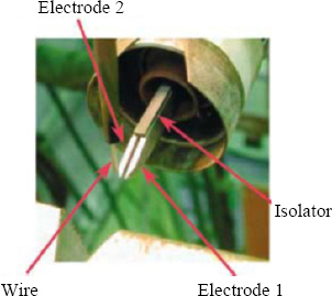
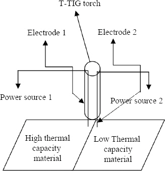
2.1 T-TIG welding process
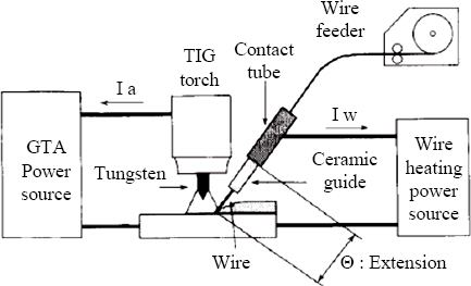
2.2 Hot filler wire
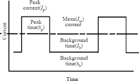
2.3 Pulsed Heat Input
3. Literature Survey
Table┬Ā1
| Sr.No. | ŌĆāŌĆāŌĆāŌĆāŌĆāRemarks |
|---|---|
| 1. | Arc pressure of T-TIG welding process was measured by CCD(Charged Coupled Device) and up to 600 mm/min welding speed was achieved for Q235 2mm thick plate2). |
| 2. | T-TIG welding process was used to weld 9% nickel steel PCLNG storage tank and compared with SAW3). |
| 3. | T-TIG welding process was used to clad on low carbon (S235JR) parent material by hot wire T-TIG process with nickel base alloy and less ferrous particle was observed 4). |
| 4. | Arc pressure was measured in T-TIG welding process when 6mm plate of Q235 material was welded with 240mm/min welding speed and current of 200+200 A. The welding was found without appreciable welding defects5). |
| 5. | Arc separation effect was found out on temperature field, plasma flow, peak temperature and arc voltage in T-TIG welding process. Effect of 4% oxygen dilution in argon gas resulted arc restriction and more penetration9). |
| 6. | Auto genus tandem TIG welding was done on 1.5mm thick 409L stainless steel with 3 m/min. speed with good control on microstructure and higher tensile strength10). |
| 7. | Arc length and distance between two electrodes were examined to find the effect on peak temperature and temperature distribution in T-TIG welding process. At the center between two electrodes maximum temperature was recorded11). |
| 8. | 2-D numerical model was developed for T-TIG welding process to describe arc characteristics. Higher peak temperature was found in case of shielding gas as helium than argon12). |
| 9. | Bead on plate welding was done by T-TIG welding process for mild steel with 600A current and 1.2mtr/min. welding speed to investigate the bead for different electrode distance13). |
| 10. | A numerical model was developed to investigate the behavior of arc and weld pool considering metal vapor concentration in T-TIG welding process14). |
| 11. | Ultrasonic excitation was generated to improve the weld quality of T-TIG welding process. Finer grain structure and better tensile strength was found for SS 304 material15). |
Table┬Ā2
| Sr.No. | ŌĆāŌĆāŌĆāŌĆāŌĆāŌĆāRemarks |
|---|---|
| 1. | A 3D CFD (Computational Fluid Dynamics) model was developed for weld pool geometry. A comparison was made for plate on bead welding between cold wire and hot wire TIG welding process for mild steel16). |
| 2. | Effect of post weld heat treatment parameters on the impact strength and hardness was investigated for hot wire assisted TIG welded joints of SA213-T91 steel. Remarkable recovery of toughness and hardness was observed and compared with cold wire TIG welding process17,18). |
| 3. | Inconel 625 alloy was overlayed on AISI 410 plate with hot wire pulsed TIG welding process and Fe content was measured by 1.83% after second layer19). |
| 4. | New method of heating the filler wire was developed by secondary arc for low resistance wire like copper and aluminum and 95% increment in deposition rate was found. Microstructure was examined with and without hot wire for HS201 filler wire with TIG welding process20). |
| 5. | Comparison of hardness was done between cladded low carbon steel with Stellite 6 and austenitic stainless steel. With cladded low carbon steel with Stellite material, hardness number was found 420 as compared to 200 on SS316 with TIG process21). |
| 6. | Relationship between the current and wire feed rate was devised to increase the melting rate. It was found that this relationship is independent from plate thickness with TIG welding process22). |
| 7. | Relationship between hot wire welding parameters and weld bead geometry was found. For the welding of low carbon steel welding, 200% increment in metal deposition rate was found with hot wire TIG welding process7). |
Table┬Ā3
| Sr.No. | ŌĆāŌĆāŌĆāŌĆāŌĆāŌĆāRemarks |
|---|---|
| 1. | Optimum pulsed TIG welding parameters were determined for C-276 material. Depth of penetration was selected as response and found that peak current is the most significant parameter for penetration23). |
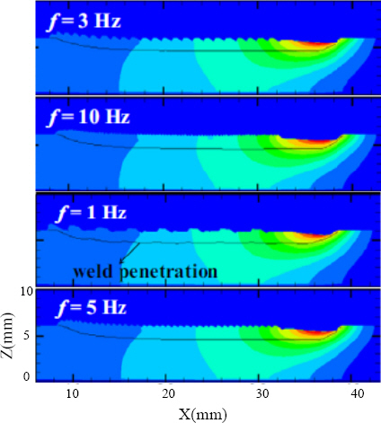
| 2. | For AISI 304L, depth of penetration was optimized for both low frequency and high frequency TIG pulsed welding. At high frequency, more penetration is observed as compared to lower frequency24). |
| 3. | 15CDV6 and SAE4130 were successfully welded with inter pulse high frequency TIG welding process. The ultimate and yield tensile strength was measured after post weld heat treatment25). |
| 4. | Optimized pulsed TIG parameters were found out for bead geometry of Ti-6Al-4V by statistical design26). |
| 5. | Analysis of mean and RMS value of peak current was done on the SAE 1020 plate where bead width and penetration were investigated27). |
| 6. | Effect of pulsed TIG welding parameters was investigated on penetration and ripple formation when welding was done on 304L material28). |
| 7. | Hastelloy (C-276) material was investigated in term of microstructure and ductility which was welded by pulsed TIG and TIG. Autogenus pulsed TIG welding was found superior due to absence of micro segregation29). |
| 8. | Comparison was made between pulsed and TIG welding process for grain structure refinement30). Increment in grain refinement was found in pulsed TIG when pulse frequency increases for Ti-6Al-4V as base metal31). |
| 9. | Dissimilar material welding was done between Ti-6Al-4V and Aluminum 7075 with filler material as AA 4047 by pulsed TIG welding process. Optimized pulsed TIG welding process parameters were found out for obtaining strength and hardness32). |
| 10. | Pulsed TIG welding was performed between AISI 904L and Monel 400 with ERNiCu-7 and ERNiCrMo-4 filler metals. Fracture was found at HAZ of Monel 400 due to partially melted zone33). |
| 11. | Dynamic heat source model was developed in which parabolic model was selected for background current and Gaussian distribution model was selected for peak current. It was experimentally validated that parabolic model during background current was more accurate34). |
| 12. | A unique finite element model was developed to handle the cathode, arc plasma and anode region for pulsed TIG welding process. Heat transfer, fluid flow and electromagnetic fields were taken as responses. For the same heat input as compared to TIG welding pulsed TIG welding gave larger weld pool35). |
| 13. | Prediction of porosity was investigated by arc spectral. Hydrogen and argon content were measured from arc spectral and used to predict the porosity when A506 Al-Mg was welded by pulsed TIG welding process36). |
| 14. | A plate of Inconel 617 was welded by pulsed and constant current TIG welding to compare the microstructure and impact strength. Finer grain with better impact strength was found in case of pulsed TIG welding process37). |
| 15. | An algorithm was developed which is capable of predicting 3-D weld pool parameters from one weld bead image for pulsed TIG welding process38). |
| 16. | Dilution of 1% nitrogen was made in argon gas to investigate the effect of delta ferrite in the austenitic phase when welding was done by pulsed TIG welding for AISI 304L steel. Addition of nitrogen lowers the value of peak current required to compensate higher speed39). |
| 17. | A numerical model was generated for pulsed current TIG welding process to simulate penetration and weld bead width. It was found that high welding speed can be achieved by appropriate high frequency without affecting penetration and bead width for 304L stainless steel40). |
| 18. | It was investigated that more penetration can be achieved with lower heat input as compared with the constant current welding process. Some guidelines were given for the values of the pulse duty cycle for various thickness range41). |
4. Effect of individual process parameters on welding
4.1 Pulsed power source parameters influencing weld bead properties.
4.1.1 Effect of pulsed welding process parameters on mechanical properties
4.1.2 Effect of pulsed parameters on metallurgical properties
4.1.3 Effect of pulsed parameters on weld bead geometry
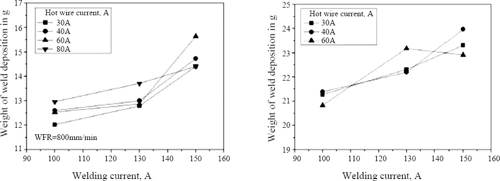
4.2 Hot wire welding parameters influencing weld bead properties
Table┬Ā6
| Effect on welding \ HW welding parameter | Weld bead geometry | Microstructure | Impact strength | Deposition rate |
|---|---|---|---|---|
| Increment in wire temperature31,56) | Weld bead increases and reinforcement decreases | Coarse grain | Deceases | Increases |
| Increment in wire stickout and decrement in wire diameter31) | NA | Coarse grain | Decrease | Increase |
| Increment in wire feed rate at constant arc current and hot wire current57) | Bead width and depth of penetration decreases | NA | NA | Increases |
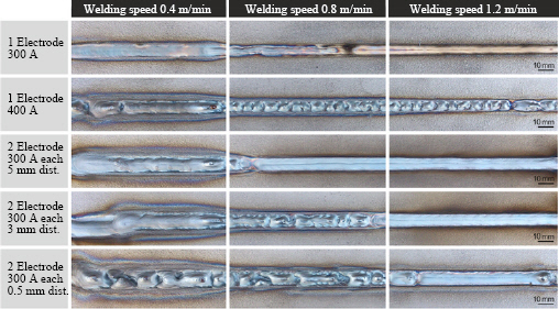
4.3 T-TIG welding parameters and its effects on welding
4.3.1 Effect of leading and trailing arc current
4.3.2 Effect of distance between two arcs
4.3.3 Effect of polarity of two electrodes
Conclusions
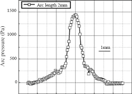
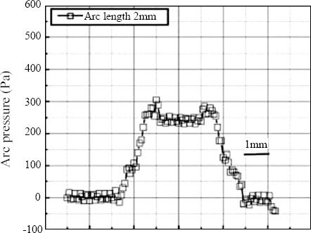
T-TIG welding is developed to increase the current capacity of electrode and thus to increase the metal deposition rate. In single electrode TIG welding process as current increases, arc pressure increases. This unstable arc causes welding defects like undercut and burn through. But T-TIG welding process reduces arc pressure drastically when appropriate distance is kept between two electrodes. As this process is used at high speed, maximum advantage can be achieved in automated welding.
It is observed that most of the heat from TIG arc plasma is utilized to heat the filler metal as well as base material from room temperature to melting point temperature. By using hot filler wire, requirement of heat from plasma can be reduced and deposition rate can be increased.
In pulsed welding the net heat input is lesser than constant current welding process. This reduces the grain size and increases impact strength. From literature review it is observed that it also increases the depth of penetration, provides good strength for dissimilar material by thermal pulsing at high frequency.
So, there is a high potential that deposition rate can be increased drastically by combining hot wire with T- TIG welding process. And if pulsed power source adds into it then there is a good potential to weld dissimilar materials, to obtain control on grain size and weld bead productively. Automated T-TIG can be an attractive option to replace SAW welding process for cladding due to lower dilution, optimized bead height and highly control on parameter resulting an exceptional weld quality
However, the limitation of integration of above three processes is high capital cost and large number of influencing process parameters involved. So, large numbers of experiments are required to identify the relationship between process parameters and on output response like mechanical properties, weld bead geometry, etc.
 PDF Links
 PubReader
 ePub Link
 Full text via DOI
 Download Citation
 Print
Print