Innovative 3D-Manufacturing of Complex Ceramic Parts by Means of Commercial Digital Light Processing Apparatus
Article information

Abstract
Additive Manufacturing technologies have been acknowledged for years as tremendous processing routes for the production of parts with complex shape. While the economic Digital Light Processing (DLP) technology was initially restricted to the production of photopolymer materials, it has a great potential for the manufacture of ceramic and metallic parts, half way between direct prototyping and the conventional powder processing route. The method consists in preparing a powder-loaded photopolymer slurry by conventional ball milling, processing green composite parts by DLP and carrying a debinding and sintering heat treatment. The present report investigates the preparation of a suitable slurry and evaluate the printability by DLP. It was found that viscosity of the slurry significantly increased with increasing powder contents, particularly over 25 vol.%. A 28 vol.% Al2O3 powder containing green composite was successfully processed using a commercial DLP apparatus. However, higher loads of powder are required to allow for appropriate sintering, which suggests optimization of the slurry by addition of solvents and use of finer powder particles to reduce viscosity and enhance printability.
1. Introduction
Additive Manufacturing (AM) has become unavoidable in the field of modern manufacturing, sometimes opportunely qualified as revolutionary. Although the outstanding potential of AM and its many different technologies is rarely questioned, the maturity of this somewhat innovative approach is debatable and efforts are constantly made to address the current issues. Of these issues, one may mention the low processing rate, high related costs or properties anisotropy which are usually common to all AM technologies when compared to conventional manufacturing. Simply stated, although AM offers exceptional opportunities in terms of parts complexity and customization, it is still today slow, expensive and unreliable1-10). ASTM International created in 2009 the ASTM committee F42 on Additive Manufacuring Technologies to define and separate AM technologies into seven categories11). Those categories and their many different technologies essentially differ by the power source, the method, the base material nature and form.
For manufacturing metallic and ceramic products, powder bed fusion (PBF) and directed energy deposition (DED) decidedly emerged as the preferred approaches for many applications12-15). On the one hand, PBF processes such as Selective Laser Melting/Sintering (SLM/SLS) and Electron Beam Melting (EBM) offer outstanding opportunities in terms of complex design versatility and materials properties. PBF technologies involve the precise deposition of a pre-alloyed powder layer onto a building platform, selective melting or sintering of the powder according the CAD profile, lowering the building platform by one layer thickness for the subsequent deposition of a new layer of powder. The process is repeated until the entire part(s) has/have been built. On the other hand, while DED processes such as Direct Metal Deposition (DMD) and Direct Metal Laser Sintering (DMLS) also provide design freedom, they are particularly attractive for their repairing or remanufacturing abilities. In these technologies, pre-alloyed powders are delivered through a moving co-axial nozzle equipped with the power source and the material is melted or sintered as it is being deposited. Although extraordinarily appealing for their undisputed performances, these complex technologies are usually very expensive with equipment costs generally in the range of six to seven digits numbers in US dollars. For this reason, alternative more economical resolutions have been studied in hope of achieving comparable results.
Stereolithography is commonly considered to be the first viable AM technology, originally dedicated to Rapid Prototyping. It consists in the selective polymerization of a photosensitive polymer to build parts layer upon layer. Digital Light Processing (DLP) in particular utilizes a commercial projector to project the image of the layer onto the bottom of a VAT containing the liquid photopolymer which would cure upon sufficient exposure. DLP is praised for its simplicity, the high definition allowed for the processed parts (as opposed to Fused Deposition Modelling (FDM) for example) and rather low cost. Although this approach does require a photopolymer by essence, its potential for the fabrication of a ceramic and metallic components have been recognized early. The general concept is borrowed to conventional powder processing technics: a powder-containing UV- curable slurry is processed by DLP to produce a composite material consisting of cured polymer into the desired parts shape containing sufficiently high content of ceramic/metallic powder to be subsequently debinded and sintered into a dense ceramic/metallic component. The general sketch of the method is shown in Fig. 1. There are only few references in the literature claiming viable procedures for this purpose either for the production of a composite, such as an electrically conductive16,17) or fiber/particles reinforced polymer18), or all the way to sintered ceramics/metals19-26). These studies exposed the principal obstacle related to this concept. On the one hand, processability of the UV-curable slurry by DLP, due to the nature of the process, is only possible if the said slurry exhibits a viscosity lower than a maximum value often set to 3000 cP and allows for bonding between consecutive layers. On the other hand, the powder content which influences the previously mentioned criteria must be sufficiently high to allow for appropriate sintering into dense ceramic/metallic parts. For these reasons, alternative apparatus combining DLP and Tape Casting technologies have been developed particularly to address issues regarding viscosity. However, the viability of using an unaltered commercial DLP machine is still debatable.
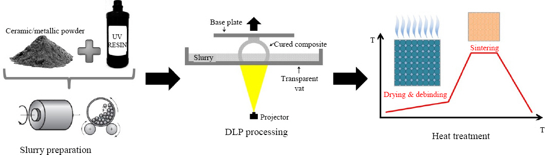
Comprehensive sketch of the proposed methodology for the innovative production of metallic/ceramic parts by means of digital light processing
In the present paper, the possibility of preparing an Al2O3-powder containing UV curable slurry suitable for processing with a commercial DLP machine is studied. Preparation of the slurry, focusing on including as high content of powder as possible, is described. Processing of the slurry by means of a commercial DLP is also described. The results highlight the compromise between processability of the slurry and amount of ceramic powder allowed. The present report does not address experimentally the last step of debinding and sintering of the green composite into a dense ceramic part. Although it is briefly discussed in conclusion, future work will focus on this theme.
2. Materials and Method
2.1 Digital Light Processing apparatus
The DLP machine used in the reported study was a commercial semi-professional equipment manufactured by the Korean company Gen Tech Korea. The apparatus was customized to accommodate a small size VAT to handle small quantities of resin/slurry. Thereby, only about 50 ml of slurry was sufficient for printing. The equipment functions as a conventional DLP machine. Digital Light Processing (DLP) is a photopolymerization process, which involves selective solidification of liquid curable resins by ultraviolet radiation. Upon irradiation, the resin undergoes a chemical reaction to become solid. The photopolymerization process works with a commercial DLP projector as the UV light source. The projector is mounted into the lower part of the machine body. The resin is kept in a reservoir (VAT) characterized by transparent glass or polymer base sitting on the top of the projection unit. The cross section of the actual layer is projected from below on the lower surface of the resin and initiates the solidification simultaneously. An upside-down stainless steel building platform dips into the resin from the top, leaving the space of one layer thickness between the transparent bottom and itself. After solidification of the layer, the platform is raised by 5 mm (adjustable) and lowered by the same distance minus one layer thickness, making space for the material of the subsequent layer. The process is repeated until the part is produced layer by layer.
2.2 Raw materials
The photopolymer used in the present study, Clear Hercules resin, was a colorless transparent acrylate-based commercial UV-curable resin produced and provided by the DLP equipment manufacturer under the. The density of the resin given by the manufacturer was 1.08 ~ 1.12 g/cm3, and the viscosity at 60 rpm and 25 °C was given at 50 ~ 70 cP. The composition of the slurry, which is not disclosed for proprietary consideration, typically included: a free radical-polymerizable monomer, an effective amount for initiation of a photosensitive initiator, an effective amount of an inhibitor system dissolved in the monomer and additives such as polymerization accelerators, diluents, viscosity regulators and plasticizers. The curing time with the specific commercial DLP machine was 5~6 seconds for a 0.5 mm layer.
The powder used for the preparation of the slurry was an Aluminum Oxide (α-Al2O3) nano-powder provided by Skyspring nanomaterials. The purity of the powder specified by the producer was 99.99 % with traces of K, Na, Ca, Mg, Fe, Si, Ti and Cu below 20 ppm. The given particle size distribution was d50 = 0.3 ~ 0.8 μm, the specific surface area 6 ~ 9 m2/g and the true density 3.95 g/cm3. The powder had not been subjected to de-agglomeration and was used as received for better convenience at the expense of performance. The actual particle size distribution of the as-received powder was measured (Malvern Instruments Mastersizer 2000). The morphology of the powder was given by the supplier. The results displayed in Fig. 2 showed that the as-received powder was considerably agglomerated with a large number of aggregates larger than 10 μm. According to the particle size analysis results, the actual size distribution of the as-received powder was d0.1 = 0.505 μm, d50 = 2.065 μm and d90 = 57.895 μm. This indicates that de-agglomeration is highly suggested. It is reasonable to assume that ball milling used for the preparation of the slurry, as described later in section 2.3, significantly broke out aggregates and reduced the average particle size. Nevertheless, de-agglomeration either by ultrasonic means or ball milling into a solvent is recommended. Finer particles with higher surface-are-to-volume ratio result in better stability of the solid loading in suspension in the slurry, better homogeneity and better sintera- bility. However, this also increases viscosity and decreases cure depth requiring the use of thinner layers24). Under such consideration, it appears that sub-micrometric powders are more appropriate.
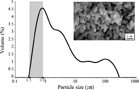
Particle size distribution of the as-received Al2O3 powder showing the significantly high particle size compared to the specifications (highlighted in light gray), therefore suggesting a de-agglomeration step before preparation of the slurry. The SEM micrograph of the powder given by the supplier was inserted
An additive was added to slurry to serve as a surfactant (Surface Active Agent). Surfactants are key to ceramic powder processing and significantly influence dispersion, wetting, deflocculation, etc. A surfactant is basically an additive that actively modifies (or coats) the particles surface. Menhaden fish oil (MFO), which is one of the most common dispersants used in Tape Casting, was presently used for cost, availability and environmental considerations.
2.3 Preparation of the slurry
The slurry for DLP processing into parts consisted of UV-curable resin, alumina powder and MFO. Proper combination of the components was carefully studied using a simplified method based on the Response Surface Methodology (RSM) which consists in varying process parameters and recording responses27-30). The parameters used were the Al2O3 powder content and the MFO content. The responses were homogeneity, settling time and viscosity. Three levels of MFO content were studied: 1 vol.%, 5 vol.%, 10 vol.%. These values of MFO corresponded to the content in vol.% with respect to the volume of powder, not the total volume of the slurry. Although not described in the present report, results showed that increasing the amount of MFO had insignificant effect on settling and homogenization while the viscosity of the slurry significantly increased. Therefore, only results with 1 vol.% MFO content are presented in the following for better convenience. Five levels of powder content were studied: 15 vol.%, 25 vol.%, 28 vol.%, 30 vol.% and 35 vol.%.
Approximately 50 ml of the different blends were carefully prepared directly into 100 ml cylindrical glass pots. Conversion charts were appropriately designed to translate volume contents into mass and a high precision balance (SciLab Korea WBA-320 Hi-Precision Lab Balance) was used to precisely add each ingredient to the slurry. The pots were subsequently sealed tightly to avoid leaks and contamination. Conventional tumbling ball milling (DAIHAN-brand® programmable ball mill BML-2) was used for blending. A constant rotation speed of 100 rpm was used for 24h for all slurry to ensure appropriate dispersion and homogenization. To this end, 5mm diameter alumina balls were added in the pots to an extent of approximately 10 % of the total charge.
2.4 Viscosity
The viscosity of each slurry was systematically measured at 24 °C (DAIHAN-brand® standard rotary viscometer WVS-2M) shortly after ball milling. Viscosity was measured with different spindles and rotation speeds. For a Newtonian fluid, the viscosity μ is constant at a given temperature and can be defined as the ratio between shear stress over shear rate according to Eq. (1)31):
where μ is the viscosity, τyx is the shear stress and ˙γ is the shear rate. The actual viscosity of the pure photopolymer resin was measured and was found to behave as a Newtonian fluid with μ=60cP.
As expected due to the significant load of solid powder, the powder-loaded slurries exhibited a non-Newtonian behavior (specifically pseudoplastic or shear-thinning fluid). For this reason, viscosity was not constant when varying shear rate. This is evidenced in Fig. 3 for a slurry composition of 28 vol.% of powder and 1 vol.% of MFO where shear stress increased with shear rate, and it is consistent with previous reports20). For such non- Newtonian fluids, the power law model is often used to represent the relationship between shear stress and shear rate according to Eq. (2)31):

τyx = f(˙γ) plot for the slurry containing 28 vol.% of Al2O3 nano-powder and 1 vol.% of MFO. The power regression is detailed to determine the consistency index k which is defined here as the viscosity of the slurry for a shear rate ˙γ = 1 s-1
where n is the flow behavior index and k is the consistency index. Eq. (2) can be conveniently rewritten in the form:
where η=k˙γn-1 is referred to as the apparent viscosity. In order to compare the viscosities of slurries with different compositions defined above in section 2.3, the values of viscosity for each slurry was considered in the present study as the apparent viscosity as defined in Eq. (3) for a shear rate ˙γ = 1 s-1. In other words, the viscosity for all slurry was defined in the present study as the constant k in Eq. (2). To this end, for each slurry, the viscosity was measured at different shear rate (proportional to the spindle geometry and rotation speed), the curve τyx = f (˙γ) was plot and the constants k and n defined as the apparent viscosity for a shear rate ˙γ = 1 s-1 and the flow behavior index, respectively, were calculated with a power regression. An example is given in Fig. 3 for a slurry composition of 28 vol.% of powder and 1 vol.% of MFO.
2.5 DLP processing
The printability of a selected number of slurries, preferably with higher powder contents, was tested by optimizing the DLP process parameters. These parameters were specifically the layer thickness, the layer curing time and the building strategy. Small cylindrical specimens with an approximate diameter Ø = 12 mm were produced vertically. For printing slurries with a content of powder ≥ 25 vol.%, an approximately 5 mm all-resin pedestal was necessary to ensure appropriate bonding between the specimen and the building platform. In absence of this polymer pedestal, in other words when the slurry was printed directly onto the stainless steel building platform, bonding was too weak for the printing specimen to stick to the building platform causing it to fall prematurely under its own weight after printing a few millimeters. DLP processing of a cylinder pedestal (Ø = 25 mm and h = 5 mm) was therefore carried out with pure photopolymer resin. The VAT was then thoroughly cleaned and subsequently filled with a powder-loaded slurry of a given composition. The building platform was finally levelled so that the top of the pedestal would contact the bottom of the VAT at the zero position before printing of the green composite began. Fig. 4 shows a 25 vol.% powder-containing green composite after printing.
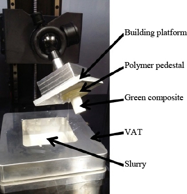
Photograph of the setup after printing a green composite from a slurry containing 25 vol.% of Al2O3 nano-powder
3. Results and Discussion
3.1 Viscosity of the slurry
The apparent viscosity of the powder-containing slurries, defined earlier in section 2.4 as the consistency index k for a shear rate ˙γ = 1 s-1, is given Fig. 5. As it could be expected, the apparent viscosity increased when the powder content increased. While the apparent viscosity increased moderately at low powder content, a great rise was observed over 25 vol.% of Al2O3 powder. Slurries with as much as 35 vol.% of powder were tested, though the viscosity of the slurry was tremendous so that it could not be measured and ball milling failed. As mentioned in introduction, the maximum viscosity of the slurry to allow for printability by DLP is often set at 3000 cP21). However, some studies reported powder- containing slurries with significantly higher viscosity suitable for some type of stereolithography, and maximum limit of viscosity as high as 5000 cP20) and even 10000 cP16). These numerical values have little sense per se, as viscosity significantly varies with temperature and shear rate. Nevertheless, taking arbitrarily this value of 3000 cP for maximum viscosity limit for printability with the commercial DLP apparatus used in the present study, the results of viscosity displayed in Fig. 5 suggest that a maximum of 39 vol.% of powder content in the slurry allows parts to be printed by DLP under current conditions. This value 39 vol.% of powder is however low to allow for appropriate debinding and sintering to high parts density as intended according to the method outlined in Fig. 1. This upper limit may conveniently be raised by different method. Addition of a diluent, such as the popular methyl ethyl ketone (MEK) could significantly decrease the viscosity of slurry, though at the expense of printability due to lower content of photosensitive polymer in the slurry. Another approach could be to adjust temperature during DLP processing as it is known that viscosity significantly decreases with raising temperature. Finally, the commercial acrylate-based photopolymer resin used in this study had not been optimized for the purpose of producing green composite parts. The viscosity of the resin was measured at μ = 60 cP. The use of an appropriately low viscosity photosensitive polymer resin could allow for higher powder content. Finally, it is believed that a de- agglomeration procedure to decrease the effective particle size of the powder, as discussed earlier in section 2.2, would also significantly reduce viscosity. Future works will explore these issues.
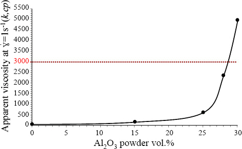
Viscosity, defined as the consistency index k for a shear rate ˙γ = 1 s-1, as a function of the Al2O3 powder content
3.2 Printability of the slurry
Several attempts were carried out to successfully print different slurries with different compositions. Only successful productions, to some extent, are reported presently. Additional printing parameters have also been considered although not conclusively studied at present. Most importantly, the layer thickness and light source intensity (with regards to the depth of cure), and the building platform lift sequence (with regards to the viscosity of the slurry) may be cited. As previously mentioned in section 2.5, a polymer pedestal was found necessary to ensure bonding of the printed green composites to the building platform in all the cases and was therefore systematically applied. Optimization of the building strategy was studied first on slurries containing 25 vol.% of powders. It was found that the building strategy should include two different strategies. Fig. 6(a) shows a green composite cylindrical part containing 25 vol.% of Al2O3 powder successfully produced with the commercial DLP used in this study. The appropriate strategy was printing first a “strong” base with layers thickness of 0.2 mm with a curing time of 12 s for each layer. The strong base should be at least 5 mm thick. Afterwards, the layer thickness and curing time were reduced to 0.1 mm and 8 s, respectively, to print the bulk. In absence of this “strong” base, the printed greens either fractured, bent or separate from the building platform despite the polymer pedestal. Specimens produced with this strategy showed good dimensional accuracy and resolution, as shown in Fig. 6(a). Never- theless, the layers could be clearly observed, suggesting that resolution along the building direction may be limited. Fig. 6(b) shows a green composite cylindrical part containing as much as 28 vol.% of Al2O3 powder. The strong base was printed with a layer thickness of 0.1 mm with a curing time of 15 s, while the bulk was printed with reduced curing time of 8 s. Although the process was a success and the specimen was resistant and consistent to the original design, the quality was decidedly lower in this case. The layers were decidedly more visible and the resolution was clearly lower. Processing slurries with as much as 30 vol.% of powder was substantially pursued unsuccessfully. Attempts failed primarily due to insufficient bonding between layers and excessive viscosity impeding proper flowing of new material for subsequent layers processing. This was consistent with criteria discussed previously in section 3.1.

Cylindrical green composite specimens (Ø = 12 mm, h = 12 mm) successfully produced by DLP with a content of Al2O3 powder of (a) 25 vol.% and (b) 28 vol.%
In order to assess the significant difference in printing resolution between pure polymer and green composite containing 28 vol.% of Al2O3 powder, resolution test plates were produced (Fig. 7). While the test plate in Fig. 7(a) produced with the pure Clear Hercules photosensitive resin exhibited high resolution with fine detailed patterns, the composite test plate in Fig. 7(b) produced with a 28 vol.% Al2O3-containing slurry showed a clearly lower definition. In particular, it is clear in Fig. 7(b) that smaller cavities or channels were not properly defined. This was due to the high viscosity of the slurry which did not flow readily causing it to clog smaller channels, therefore significantly decreasing printing resolution. This is noticeable since one of the advantage of the DLP process is its high resolution compared for example to FDM. Considering that subsequent heat treatment to remove the polymer binder and sinter the ceramic would inevitably lead to contraction and distortion, the lower the powder concentration the higher that is, significant limitation in parts design is to be expected.
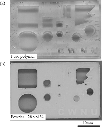
Optical scans of resolution test plates produced by DLP for (a) pure polymer and (b) composite containing 28 vol.% Al2O3 powder
Although it was not discussed nor investigated in details in the present study, it is known that high contents of ceramic powder in the slurry cause significant light scattering and reduces the depth of cure16,17,19,21-23,26). This was one of the causes for adjusting the building strategy described earlier and for the lower definition obtained when increasing the volume of powder.
3.3 Possible heat treatment of debinding and sintering
As hinted in the general sketch in Fig. 1, the subsequent heat treatment process consists in two steps. Although the scope of the presently reported study was not to design and investigate the heat treatment process, a few preliminary details are discussed briefly. The first step is the debinding process in order to remove the polymer binder, the cured photopolymer in the present case. Both temperatures and heating rates are critical. In particular the binder burnout stage must be carefully controlled to avoid delamination, blistering, bloating and cracking. Differential Scanning Calorimetry (DSC SDT Q600, 1 °C/min) analysis was carried out with a cured (printed) pure Clear Hercules photopolymer to assess the different steps of the debinding stage. The results of DSC analysis are shown in Fig. 8. The results in Fig. 8 show that critical temperatures of approximately 350 °C and 550 °C correspond to the start and end of the polymer burnout or debinding stage, respectively. It is therefore recommended to initially heat the as-built composite at a rate of about 1 °C/min to the temperature of 350 °C. The heating rate should subsequently be reduced down to 0.1~0.5 °C/min between 350 °C and 550 °C to avoid deformation, appearance of bubbles or cracking. Significant shrinkage is to be expected in function of the powder content.
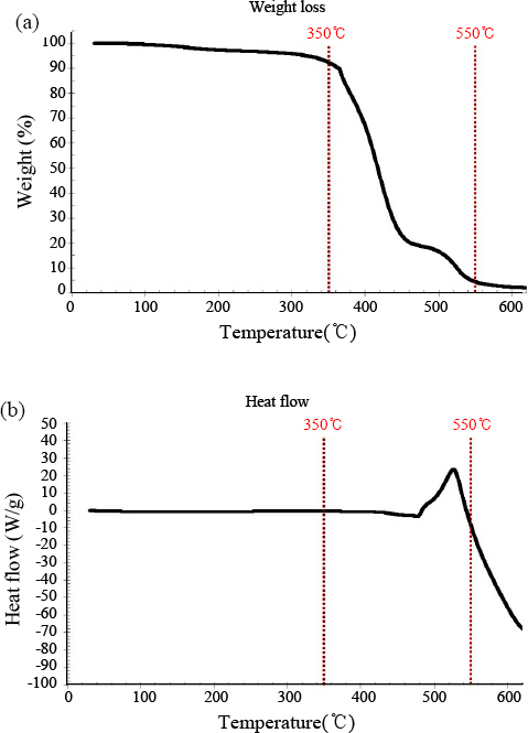
Differential Scanning Calorimetry (DSC) results of the cured pure photopolymer showing (a) the weight loss and (b) the heat flow as a function of the temperature
The second step of the heat treatment corresponds to the sintering stage. This should conveniently be immediately carried out after the debinding stage. Samples may be heat heated more rapidly up to the sintering temperature at a rate of 5~10 °C/min. The sintering temperature depends on the actual material and is typically between 70 and 90 % of the melting temperature. For the α-alumina powder used in the present study, the recommended sintering temperature is often comprised between 1300 °C and 1600 °C for times between 1 h and 5 h according to the powder size, distribution and volume fraction in the slurry21-24,26). Note that high concentrations of powders is preferred for successful sintering, often higher than 45 vol.%. This suggests that the previous steps of the process, in particular the preparation of a printable slurry with higher content of powder using diluents is necessary. Finally, a slight pressure for example immersing the composite into an alumina of zirconia balls bath may be necessary to prevent distortion.
4. Conclusion
The reported study investigated the feasibility of using Digital Light Processing, an AM technology designed for the production of polymer parts and components, for the alternative processing of ceramics and metals. The method involves the preparation of a slurry consisting of a photosensitive polymer necessary for DLP processing in which a significant load of powder material, presently an Al2O3 nano-powder. The viscous slurry is then conventionally processed by DLP into complex parts. At last, the as-built green composite is subjected to a carefully designed heat treatment of debinding to remove the polymer binder and sintering into dense ceramic/metallic part. In the present paper, preparation of said slurry and printing of the green composite were examined. It was found that addition of powder material to the photosensitive resin significantly increased viscosity, particularly above 25 vol.% of powder content. Printability of the slurries by DLP was directly connected to their viscosity. The results suggested that although a commercial DLP equipment shows encouraging potential for producing green composite parts containing high content of non-polymer material, great care must be taken in preparing the slurry to accommodate the inevitable compromise between viscosity and powder content. While a green composite containing 28 vol.% of Al2O3 powder was successfully produced, the parts resolution was unacceptable considering AM and the volume of powder was certainly too low for heat treatment into a dense ceramic part. A minimum of 40~45 vol.% of powder should be targeted for sinterability. This implies that powders should be appropriately de-agglomerated, viscosity of the photopolymer resin should be as low as possible, solvents should be properly added to the slurry to reduce its viscosity, temperature should be carefully monitored and controlled during DLP processing and more.
Acknowledgements
이 논문은 2016년도 창원대학교 신임교수 연구경비 지원에 의하여 연구되었음
This research was supported by Changwon National University in 2016.