Effect of Aluminum on Thermally Induced ε-Martensite for Fe-Mn-C TWIP Steels
Article information

Abstract
Cold-rolling of hot-rolled plate of Fe-18.7Mn-0.61C-1.4Al (Al-TWIP) steel was identified with an austenite single phase through the entire thickness, and that of Fe-17.8Mn-0.57C (TWIP) steel was composed of ε-martensite and austenite phases from the surface to a thickness of ~45 μm. Electron back-scattered diffraction (EBSD), glow discharge spectrometry (GDS), and transmission electron microscopy (TEM) were conducted to investigate the ε-martensite transformation of TWIP steel. In TWIP steel, thermally induced ε-martensite transformation was produced since the surface austenite stability decreased due to surface decarburization. The thickness of ε-martensite (~45 μm) was coincident with the depth at which 0.45 wt% C of TWIP steel was achieved. However, the TWIP steel with added Al increased the austenite stability of the surface layer and suppressed ε-martensite transformation.
1. Introduction
TWIP steel having high strength and formability is under active research following environmental and safety regulations in the automobile industry1-5). TWIP steel is high-manganese steel containing more than 15% manganese and mechanical twins that are generated during plastic deformation are responsible for its improved elongation, high strain-hardening rate, and excellent strength. Therefore, it has reasonable processability including weldability and can meet the requirements of the automobile industry6-11).
The major deformation mode of TWIP steel is determined by the stacking fault energy (SFE). SFE determines the plastic-deformation mode such as martensite transformation, deformation twinning, and slip modes in TWIP steel12,13). Sato et al. reported that the mechanical transformation from austenite to ε-martensite was favored for SFE lower than 20 mJ m-2, whereas the formation of mechanical ε-martensite was suppressed and deformation twinning occurred when SFE was higher than 20 mJ m-2 in Fe-Mn-Al TWIP steels14). Alline et al. calculated that mechanical twinning occurred at SFE between 12 and 35 mJ m-2 in Fe-22Mn- 0.6C TWIP steel15). Frommeyer et al. reported that mechanical ε-martensite transformation occurred at low SFE (< 16 mJ m-2) and the formation of twin deformation was favored for SFE between 16 and 25 mJ m-2 in stable austenitic phases16). ε-martensite can be produced by strain-induced transformation and thermally induced transformation (by heat treatment)17,18). Thermally induced ε-martensite is produced with lower SFE than strain-induced ε-martensite19).
The primary factors that determine SFE are chemical composition and deformation temperature12,13). Aluminum (Al) is a very effective element for increasing SFE and suppresses ε-martensite transformation in TWIP steel14,20). Kim et al. reported that SFE increased by 17 mJ m-2 when 1.5 wt% Al was added to Fe-18Mn-0.6C TWIP steel13). The addition of Al was shown to inhibit ε-martensite transformation and delayed fracture when the cup deformation of Fe-18Mn-0.6C TWIP steel was conducted21). However, the reason was not studied for the ε-martensite transformation for Fe-18Mn-0.6C steels due to the addition of Al. The objective of this study is to identify the mechanism by which Al content affects ε- martensitic transformation in Fe-17.8Mn-0.57C TWIP and Fe-18.7Mn-0.61C-1.4Al TWIP steels.
2. Materials and methods
The chemical compositions of specimens used in this experiment were Fe-17.8Mn-0.57C and Fe-18.7Mn-0.61C- 1.4Al, which are referred to as ‘TWIP’ and ‘Al-TWIP’, respectively. Fig. 1 shows the detailed conditions for manufacturing the TWIP and Al-TWIP steels. Sample ingots of thickness 25 mm were fabricated using a high-frequency vacuum melting furnace. Slab reheating in air was conducted at 1200 °C for 1 h. After slab reheating, ingots were air-cooled to room temperature after hot rolling to 2.5 mm thickness and the sheets were cold-rolled to the final thickness of 1.25 mm at room temperature. Finally, the sheets were water-cooled after recrystallization heat treatment at 900 °C for 1 min to prevent carbide precipitation21).

Schematic illustration of the manufacturing conditions of TWIP and Al-TWIP steels
The specimens were mechanically polished and etched with 3% Nital solution, 10% sulfuric acid (H2SO4), and 10% aqueous sodium metabisulfite (Na2S2O5) solution. The microstructures of TWIP and Al-TWP steels were examined using light optical microscopy (LOM). Elec- tron back-scattered diffraction (EBSD), transmission electron microscopy (TEM), and X-ray diffraction (XRD) were conducted to identify the phases. XRD using a Cu-Kα target was scanned from 30 to 100°, with step size of 0.02° and scan speed of 1.0°min-1. Using a focused ion beam system, phase identification under the surfaces of specific microstructures was conducted with TEM. Glow discharge spectrometry (GDS) measured carbon, manganese, and aluminum contents from the surface in the thickness direction.
3. Results and discussion
Fig. 2 shows the X-ray diffraction patterns of TWIP and Al-TWIP steels after cold rolling followed by recrystallization heat treatment. The XRD pattern was measured 10 μm from the surface. The Al-TWIP steel indicated full austenite phase and the TWIP steel showed ε-martensite in addition to austenite. Fig. 2b is the diffraction pattern measured approximately 50 μm from the surface. Austenite single phases appeared in the XRD patterns of both TWIP steels. The formation of ε-martensite varied in TWIP steel with respect to the thickness. However, the Al-TWIP steel showed the austenite phase regardless of thickness.

X-ray diffraction patterns of TWIP and Al-TWIP steels: (a) 10 μm from the surface and (b) 50 μm from the surface
Phase analysis using EBSD was conducted to confirm martensite transformation of the surface regions in TWIP and Al-TWIP steels after polishing the surfaces approximately 10 μm to remove the scale layers. Fig. 3 shows the EBSD phase maps of the cross-sections of TWIP and Al-TWIP steels. The red-colored area of the phase map is austenite (fcc) and the green-colored area is ε-martensite (hcp). Fig. 3a shows that TWIP steel had ε-martensite from the surface to a depth of ~30 μm and the volume fraction of ε-martensite decreased while approaching the center of the specimen. Considering the removal of the outermost-surface layer (~10 μm) in TWIP steel, the thickness of ε-martensite measured using EBSD (~40 μm) was nearly coincident with that (~50 μm) measured using XRD (Fig. 2b). Al-TWIP steel indicated a single austenite phase at all thicknesses, as shown in Fig. 3b.
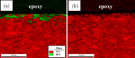
EBSD phase maps of the cross-sections of (a) TWIP steel and (b) Al-TWIP steel
Fig. 4 presents a TEM micrograph showing the cross- sectional microstructure of TWIP steel. The lath shape of ε-martensite was observed near the surface of TWIP steel (Fig. 4a). Figs. 4b and 4c show the diffraction patterns of ε-martensite (hcp) and austenite (fcc), respectively. TEM analysis confirmed the existence of ε-martensite in TWIP steel.
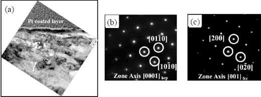
TEM micrographs of TWIP steel: (a) cross-section below surface, (b) diffraction pattern of ε-martensite, and (c) diffraction pattern of austenite
Fig. 5 shows the optical microstructures of TWIP and Al-TWIP steels measured at the position of quarter thickness. Both specimens indicated polygonal grains of recrystallized austenite and there were no indications of ε-martensite and elongated grains due to rolling. The specimens were water-cooled after recrystallization heat treatment at 900 °C for 1 min. Therefore, the ε-martensite produced near the surface of TWIP steel is thermally induced ε-martensite rather than strain-induced ε-martensite. To produce thermal ε-martensite by water-cooling, a low value of stacking fault energy (SFE) is needed near the surface of TWIP steel17-19). SFE depends on the chemical composition and deformation temperature12,13). In this study, chemical composition is the only factor affecting SFE due to which the effects of plastic deformation on the microstructure disappeared during recrystallization heat treatment.
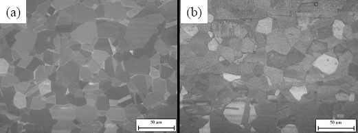
Optical micrographs after recrystallization heat treatment for (a) TWIP steel and (b) Al-TWIP steel
The cross-section chemical composition was investigated from the surface in the depth direction. GDS was applied to analyze the surface compositions of C, Mn, and Al in TWIP and Al-TWIP steels. The surface-scale layer of approximately 10 μm was removed to improve precision before GDS measurement. Fig. 6a shows the depth profile of carbon. Near the surface, the carbon contents of the TWIP and Al-TWIP steels were significantly lower than the original alloying composition. Al-TWIP steel had a larger content of carbon than TWIP steel. The carbon contents were restored to the value of 0.6 wt% while approaching the centers of the specimens. Carbon depletion near the surface was due to the decarburization that occurred at the surfaces of TWIP and Al- TWIP steels. Figs. 6b and 6c indicate the depth profiles of Mn and Al, respectively. Al and Mn contents were mostly constant in TWIP and Al-TWIP steels, regardless of thickness.
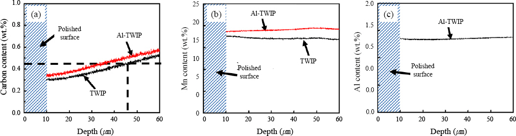
GDS depth profiles of TWIP and Al-TWIP steels for (a) carbon, (b) manganese, and (c) aluminum
Oxidation and decarburization reactions of steel materials are known to occur simultaneously in the reheating furnace22). Lee et al. investigated the oxidation behavior of Fe-18Mn-0.6C-1.5Al TWIP in a reheating furnace24). The Mn content reduced in the surface-oxidized layer because of the formation of Mn oxide, but the Al content was mostly constant throughout the thickness. The demanganized layer from the previous study had a thickness of approximately 10 μm23). However, the martensite formed in the study had a thickness of approximately 45 μm. Hence, the thermally induced ε-martensite formed in TWIP steel was not entirely due to surface oxidation in the reheating and recrystallization furnaces.
Thermally induced ε-martensite was generated because of surface decarburization in Fe-15Mn-2Cr-0.6C TWIP steel24). Schumann et al. calculated that thermally induced ε-martensite was generated when carbon was about 0.45 wt% or less in the Fe-18Mn-0.6C system19). However, the effect of Al on thermally induced ε-martensite transformation was not investigated in the previous studies18,24). Fig. 6a shows that 0.45 wt% C of TWIP steel was achieved at a depth of approximately 45 μm from the surface. The depth of 45 μm matched the thickness of ε-martensite measured by XRD (~50 μm) and EBSD phase mapping (~40 μm), as indicated in Figs. 2 and 3a. Therefore, the formation of ε-martensite on the surface of TWIP steel can be explained by the decarburization phenomenon on the surface. Surface decarburization is closely related to the manufacturing process of TWIP steels because carbon increases the austenite stability of TWIP steel by increasing SFE25). In this study, slab reheating was conducted at 1200 °C for 1 h in air. It is an essential process for the removal of dendrite structures and securing the temperature for hot rolling26,27). Surface decarburization was expected because slab reheating was processed at high temperature under oxidizing conditions.
The decarburized layers produced from slab reheating remained at the surfaces of TWIP steel and Al-TWIP steel even after the completion of recrystallization heat treatment. Kim et al. measured the SFE of Fe-18Mn- 0.6C TWIP and Fe-18-Mn-0.6C-1.5Al TWIP steels by TEM13). The SFE of Fe-18Mn-0.6C TWIP steel was 13 ± 3 mJ m-2 and that of Fe-18-Mn-0.6C-1.5Al was 30 ± 10 mJ m-2. These compositions are nearly identical to those in this study. Therefore, the SFE values of this study can be considered the same as the SFE values derived from the previous study13). The decarburized layer at the surface existed in both the TWIP and Al-TWIP steels, but the ε-martensite transformation occurred only in the TWIP steel. This was because austenite stability decreased due to decarburization at the surface of TWIP steel. In contrast, SFE increased with the addition of Al in TWIP steel and the austenite stability increased in the decarburization region, suppressing ε-martensite transformation in Al-TWIP steel.
4. Conclusions
This study investigated the thermally induced ε-martensite transformation at the surfaces of Fe-17.8Mn-0.57C (TWIP) and Fe-18.7Mn-0.61C-1.4Al (Al-TWIP) steels. The ε-martensite transformation occurred from the surface to a thickness of ~45 μm in TWIP steel. Near the surface, the carbon contents of the TWIP and Al-TWIP steels were significantly lower than the original alloying composition. Therefore, the ε-martensite transformation was caused by surface decarburization during the reheating process (1200 °C for 1 h). Decarburization reduced the SFE and austenite stability at the surface. Although decarburization occurred at the surface of Al-TWIP steel, no ε-martensite transformation was observed because aluminum increased the SFE and austenite stability in the surface region. Carbon content of 0.45 wt% was achieved at a depth of ~45 μm from the surface for TWIP steel. The depth of 45 μm coincided with the thickness of ε-martensite measured by XRD (~50 μm) and EBSD phase mapping (~40 μm).
Acknowledgements
This research was supported by a 2-year research grant of Pusan National University.