


1. Introduction
Weight reduction of automobiles is the most practical and effective method for improving fuel efficiency and reducing emissions, and is an essential technology that can complement the weight increasing trend fueled by the vehicle safety and convenience enhancement and the limitations of other fuel efficiency improvement technologies.
Since the application of aluminum alloy to hoods, trunks, tailgates, and doors, which are called moving parts in automobiles, is considered, it is necessary to join with steel but because of the limitations with employing conventional welding methods alone, a variety of different methods are being examined1) However, in dissimilar welding of Al and steel, various kinds of intermetallic compounds are generated, resulting in deterioration of weldments properties2-6). It has been reported that tensile shear strength is lowered due to the generation of FeAl5, FeAl3 and Fe3Al in the GMAW dissimilar welding between Al5052 alloy and GA steel sheet. It has also been reported that compounds such as Al13Fe4, Al5Fe2, Al2Fe, FeAl, Fe3Al and Al6Fe were generated in the laser welding of Al5052 alloy and steel plate cold commercial (SPCC) materials.
The principle of Magnetic Pulse Welding (MPW)7,8) is similar to the principle of explosive joining. However, the difference is that explosive joining joins metals using the instantaneous high impact energy generated from the explosion of explosives, whereas magnetic pulse welding is a solid-state welding process that uses the electromagnetic force generated by instantaneously discharging the high energy charged in the capacitor bank to create a high-speed collision between the two metals for the welding of metals. Therefore, there is no thermal effect, thereby no heat-affected zone, and only some plastic deformed areas are generated, so that the generation of brittle intermetallic compounds can be prevented when joining aluminum and steel.
Various types of coatings for improving corrosion resistance have been applied in industries such as automobiles. In magnetic pulse welding, the welding quality depends on the behavior of the material in the collision region, so it is necessary to consider the surface layer of the material. For automobiles, coated steel sheets are actively used in various types and quantities, so the effect of the associated coating layers should be considered when welding. In addition, coatings such as zinc, nickel, and chromium are also applied through anodic oxidation, chromate treatment, and passivation treatment. According to Bellmann9), after coating Ni and Cr using the PVD method, magnetic pulse welding was performed, and as a result, they found that the Cr coating layer was hard, making welding difficult, and Ni layer had suitable ductility, so that welding was possible.
In this study, an magnetic pulse welding process was used to fabricate the joining part between aluminum and various types of coated steel sheets and the effect of coated steel sheet during dissimilar joining was investigated through electrochemical properties test and corrosion test for the joining part.
2. Materials and Methods
2.1 Materials
As materials used for magnetic pulse welding, various kinds of coated steel sheets and 0.5 mm thick Al1050 were used. For non-coated steel sheet, steel plate cold deep drawn extra (SPCE) plate with a thickness of 0.5mm, which is a general steel, was used, and as a coated steel sheet, 0.3mm thick Zn- coated steel sheet (coating layer about 20ŃÄø) and 0.2mm thick Ni-coated steel sheet (coating layer about 10 ╬╝m) were used.
2.2 Magnetic pulse welding
As for the magnetic pulse welding, a U-shaped coil was mounted as shown in Fig. 1 and a specimen was fixed underneath for the sheet welding to conduct the welding experiment.

The magnetic pulse welding equipment consists of a capacitor bank, a high voltage charging power supply, a coil, a discharge circuit, and a high voltage switch. After charging energy to the capacitor bank with the power supply, the energy is discharged using the high voltage switch. Then, magnetic field is formed as high current flows along the working coil shown in Fig. 1, and an instantaneous magnetic field is generated within several tens of ŃÄ▓ to generate an eddy current in the material. It is the principle that the material undergoes plastic deformation by the repulsive force between the eddy current and the magnetic field.
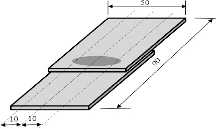
For welding, a specimen with the shape shown in Fig. 2 was used, and for the flyer material which is directly affected by the electromagnetic pulse, AI with easy plastic deformation characteristics was used and the coated steel sheet was used as the target material to be fixed underneath to perform the welding.
2.3 Corrosion test
2.3.1 Electrochemical corrosion test
To test the effect of material before immersion corrosion test of dissimilar weldment, as shown in Fig. 3, after keeping the steel material (SPCE) and the Al material out of contact, two materials of a 100 ╬╝m thick pure (99%) Ni thin plate and a pure (99%) Zn thin plate were used for joining with a conductive Ag adhesive.
For the corrosion test, as shown in Fig. 4, corrosion tester was used to test the corrosion of flat sheet materials. As for the corrosion area, a circular cell with a diameter of 45 mm was used, and a 3.5% NaCl solution was used for the corrosion solution. For the reference electrode, a KCl electrode was used for the measurement of corrosion potential at room temperature in the voltage range of -1.8V to 0.2V. The corrosion potential was measured by the Tafel method using potentiostat.
2.3.2 Immersion corrosion test
As for the corrosion test, immersion corrosion test was conducted according to NACE TM0169/G31. In the NACE regulation, as shown in Fig. 5, three tests, which are complete immersion in a solution, semi-immersion, and atmospheric exposure tests are prescribed. Considering the circumstances, for this test, corrosion test of complete immersion and atmospheric exposure were performed. As for the corrosion sample, a small hole with a diameter of about 0.2 mm was formed at one end of the Al specimen, and the specimen was hung vertically by using a string of transparent nylon to position the specimen. As the test solution, 3.5% NaCl solution as in the electrochemical test was used. The temperature was maintained at 35 ┬▒ 5 ┬░C., the total corrosion test time was 1008 hours, and the corrosion solution was replaced every 1 week.
For immersion corrosion test, as shown in Fig. 6, welded specimens werecut and used..
2.4 Evaluation of joint strength after corrosion test
After the corrosion test, the corrosivity evaluation was replaced with a tensile shear test because the specimen used in this test had a lap shape, so it was difficult to separate the corrosion loss or corrosion products for the test. Specimens were collected after 336 hours and 1008 hours, respectively, and washed with alcohol and used for tensile shear test.
3. Results and Discussion
3.1 Magnetic pulse welding
A weldment specimen as shown in Fig. 7 was fabricated through magnetic pulse welding process. The specimen shown in the figure is its flat image that was cut to the specification for the joining part corrosion test. The welding condition was 13kV of applied voltage, the distance between the flyer material and the target material was 2mm, and the heat input was about 40kJ. Heat input can be expressed as energy as below.

Here, E is the junction energy (J), C is the capacitor bank capacity (uF), V is the applied voltage (V), and B is the number of capacitor banks used.
Three types of specimens were fabricated as follows: non-coated steel sheet and Al1050 (Al-Fe), Ni-coated steel sheet and Al1050 (Al-Ni-Fe), and Zn-coated steel sheet and Al1050 (Al-Zn-Fe).
3.2 Electrochemical corrosion behavior test
Fig. 8 shows the Tafel curve of the specimen reproducing the dissimilar joining part. The corrosion potential (E-corrosion) is about -0.9V for the Al-Zn-Fe combination, about -0.85V for the Al-Fe combination, and about -0.8V for the Al-Ni-Fe combination, making the Al-Ni-Fe combination the highest and the Al-Zn-Fe combination the lowest. This is considered to be due to the fact that Ni is a noble metal compared to Zn and Fe, and has better electrochemical properties.

In addition, from the viewpoint of corrosion current, Ni is the highest, followed by Zn and Fe. These findings indicate that until corrosion begins, the corrosion resistance of the Ni coating layer is the most excellent, but once corrosion starts, the most corrosion is likely to occur in the case where Ni is used as the coating layer, and the amount of corrosion decreases when there is no coating layer.
3.3 Corrosion resistance of magnetic pulse weldment
Fig. 9 shows the results of the tensile shear test after the corrosion test for each material combination of weldment specimen. Fig. 9 (a) is the result of tensile shear test on the immersed specimen. In the case of Al-Zn-Fe, tensile shear deterioration occurred from the beginning of the corrosion test because the joining part was detached due to the early corrosion of the joining part as the corrosion test proceeded. (Fig. 10). In the case of the Al-Fe and Al-Ni-Fe combinations, the fracture did not occur in the joining part, but the tensile shear was lowered over time. Therefore, it is thought that the tensile shear strength was lowered as the Al base material corroded.
Fig.┬Ā9
Tensile test results of MPW joint after corrosion test (a) Immersion (b) Atmospheric exposure
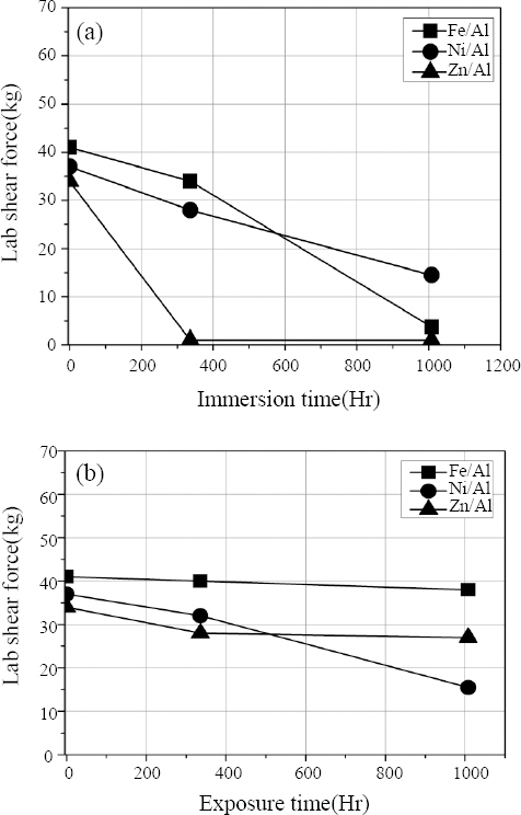

In the case of Al-Fe combination, since there was no coating, it is thought that the tensile shear strength gradually decreased as corrosion progressed, and the case of Al-Ni-Fe showed to have maintained the highest tensile shear strength and the reason for this is that as can be seen from the results of the electrochemical corrosion test, this combination has higher corrosion potential than other combinations, leading to not much progress of the corrosion. Overall, welding tensile shear strength showed a sharp decrease in the immersion specimens compared to the atmospheric exposure specimen, and this is thought to be due to the fact that the contact area and the amount of contact with the corrosive solution were higher in the case of immersion specimen. In addition, it is considered that no treatment on the side of the specimen may have led to the acceleration of the corrosion, but this needs to be verified through additional experiment.
Fig. 9 (b) is a result of the tensile shear test of the specimen exposed to the atmosphere and shows a different pattern from the immersion specimen. As shown in Fig. 10, after 1008 hours of corrosion test, in the case of Al-Fe combination, fracture occurred in the Al base and in the case of Al-Zn-Fe, joining part was detached or fracture occurred in the Zn-coated steel sheet base and in the case of Al-Ni-Fe, fracture occurred in the Ni-coated steel sheet base. In the case of Al-Fe and Al-Zn-Fe combinations, there was no change in tensile shear strength after 1008 hours, but in the case of Al- Ni-Fe, tensile shear strength was low after 1008 hours, which means that the thickness of Ni-coated steel sheet is 0.2mm, thinner than other materials, indicating faster progress of corrosion. Furthermore, since there was no coating treatment on the side in the specimen fabrication, leading to the effect of large potential difference between Ni and Fe showing faster, thereby accelerating the corrosion to proceed.
In the case of the Al-Zn-Fe combination, the thickness of the Zn-coated steel sheet is thinner than that of the Al1050 material, and the length is also short, and it is thought that the corrosion effect of Zn-coated steel sheet was large.
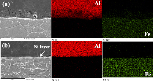
Fig. 11 shows the results of analyzing the cross section of the specimen after the corrosion test. In the case of the Al-Fe combination, there is a trace of corrosion on the Al side, and the distribution of Al is also blurred in the EDX analysis results, indicating that corrosion has occurred. On the other hand, in the case of the Al-Ni- Fe combination, there are some traces of corrosion on the Al side, but unlike the case of the Al-Fe combination, there is no remarkable corrosion pattern.
Fig.┬Ā11
SEM/EDX analysis results of MPW joints after immersion corrosion test. (a) Fe - 336hr (b) Ni - 1008hr
In the case of fusion welding, the weldments are fused and then solidified provoking a structural change , resulting in a potential difference, and thus a galvanic corrosion phenomenon occurs in which corrosion proceeds first. In the case of magnetic pulse welding, there is no fusion, so the joining part is about several to several tens of ┬Ąm, and there is almost no structural change. Therefore, in the case of magnetic pulse welding, corrosion occurs due to the corrosion potential difference between Al and Fe itself, and the Al side with a low corrosion potential is thought to be corroded first.
According to Kang et al.10), a similar tendency was found in the spot resistance weldment salt spray test, but the spot weldment tensile shear strength showed greater reduction in the GA steel sheet than that of CR steel sheet. Therefore, in the case of coated steel sheets, corrosion resistance is different depending on the corrosion environment, so it is necessary to select a coating material suitable for the environment of use, and it is difficult to conclude that the case where a coating layer is present in the joining part is always advantageous for corrosion resistance.
4. Conclusion
The dissimilar weldment specimens between Al and various types of coated steel sheet were fabricated using magnetic pulse welding process, and the following conclusions were drawn through the corrosion test.
1) As a result of measuring corrosion potential using Zn, Ni, etc. between Al and general steel sheet, the corrosion potential of the combination with Ni as the middle layer was the highest, followed by the joining part without intermediate layer and the joining part using Zn.
2) As a result of immersion corrosion test, the corrosion resistance was the highest in Al-Ni-Fe combination and the lowest in Al-Zn-Fe combination. The Al-Fe combination showed higher corrosion than the Al-Zn-Fe and Al-Ni-Fe combinations in the water vapor atmosphere exposure test.
3) In the case of Zn-coated steel sheet, the fracture mechanism and tensile shear strength for the weldment specimen were different according to the corrosion environment.
ORCID
ORCID: Byoung-Hyun Yoon: http://orcid.org/0000-0003-4683-7888
ORCID: Ji-Yeon Shim: http://orcid.org/0000-0002-2825-9423
ORCID: Bong-Yong Kang: http://orcid.org/0000-0002-7826-9873
 PDF Links
 PubReader
 ePub Link
 Full text via DOI
 Download Citation
 Print
Print