


1. Introduction
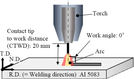
2. Experimental procedure
3. Results and Discussion
3.1 Waveform comparison according to the change of the EN pulsing ratio
Fig.┬Ā3
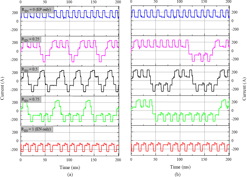
Fig.┬Ā4
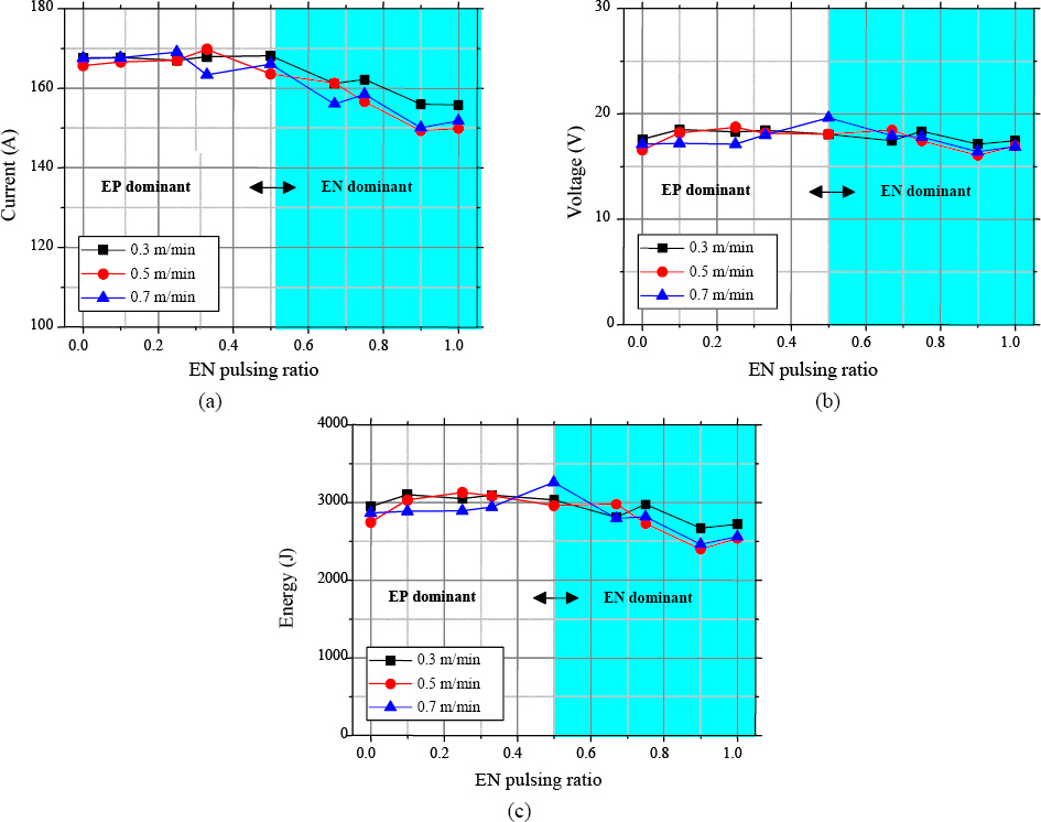
3.2 Comparison of weldability according to EN pulsing ratio change
Fig.┬Ā6

Fig.┬Ā7
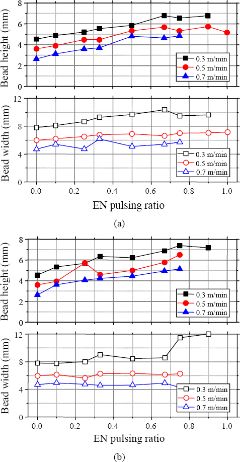
Fig.┬Ā8

3.3 Effects of EN pulsing ratio change on structure formation
Fig.┬Ā9

4. Conclusion
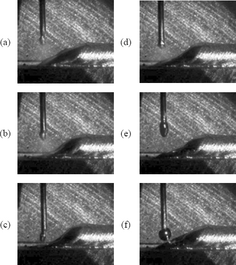
1) EN pulsing ratio change directly affects the arc concentration location, which caused a change in the amount of deposition and melting of the substrate. The droplet size was small, and the surface of the molten pool was deflected due to strong arc generation in the EP phase period. While the droplet size was large even though low input energy was supplied in the EN phase, and the arc was formed at a relatively high position compared to the EP phase period. As the EN pulsing ratio increased, the weight of the deposition tended to increase, and width tended to increase. As the repetition frequency in a cycle was increased, the ripple on the weld bead was clearly observed, but the effect of repetition frequency on the weight of the droplet was negligible.
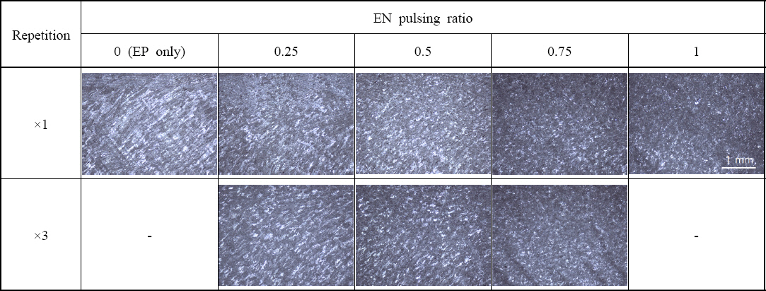
2) The effect of phase and polarity changing frequency on microstructure formation was confirmed. It is inferred that it is possible to form a fine structure under EN polarity compared to EP polarity. Because not only relatively low heat input was supplied under the condition of high EN pulsing ratio, but also because the temperature of the droplet was low due to the large amount of energy consumed to melt the wire. Epitaxial growth was observed due to the thermal overlap of the applied heat input at a low EN pulsing ratio. It was reconfirmed that anisotropic characteristics can be suppressed through the phase change, similar to the research of Fang11) and Cong12). As the frequency of phase change increased, the size of the grains decreased. When the repetition frequency in a cycle increased, the frequency of phase changes decreased. Thus, it is considered to be advantageous to reduce the repetition frequency to reduce the grain size.
 PDF Links
 PubReader
 ePub Link
 Full text via DOI
 Download Citation
 Print
Print