The Effect of EN Pulsing Ratio and Repetition Frequency on the Bead Appearance and Microstructure Evolution in Aluminum Welding using Variable Polarity GMAW
가변극성을 이용한 알루미늄 GMAW 용접에서 주기 내 EN 펄스 비율 및 반복횟수가 용접부 형상 및 조직형성에 미치는 영향
Article information

Abstract
This study addressed the gas metal arc welding (GMAW) of Al 5183 aluminum alloy using variable polarity (VP). The effects of the electrode negative (EN) pulsing ratio and repetition frequency on the geometrical features and microstructural evolution of the deposited materials were investigated and discussed. The current and voltage were manually controlled independently for each phase to evaluate the effect of the polarity change. The influence of phase and its changing frequency on the geometrical features and microstructure evolution were observed. The phase of the electrode affected the arc concentration and changed the amount of the deposited material and the dilution between the substrate. The EN phase is beneficial for making a finer structure than the electrode positive (EP) phase because of the lower heat input per unit mass. In addition, the size of the grains decreased as the phase change frequency increased. When the number of repetitions frequency increased within a cycle, the size of the microstructure was reduced. Consequently, strategies can be established to minimize the microstructure with VP-GMAW welding using a high EN pulsing ratio and low repetition conditions.
1. Introduction
As the demand for low heat input and low deformation arc welding increases, the application of cold metal transfer (CMT) power sources capable of short-circuiting are also increasing. Among them, a welding power source, which can manually apply short-circuiting under variable polarity (VP), can arbitrarily adjust the number of electrode positive (EP) and electrode negative (EN) phase within one cycle. This welding power source can maximize the functions desired by users such as a deposition amount or depth of fusion according to the target product.
VP-GMAW power source has attracted attention from researchers because of various arc behavior according to polarity1-4). Kumar5) and Park6) analyzed the arc concentration according to the polarity during AC pulsed GMAW welding and investigated the relationship with the heat input. Kiran7) mentioned that the use of AC pulse GMAW was effective in enhancing the gap bridging ability and reducing the deformation. Because the deposition amount increased by the arc concentration occurred on the filler wire. Several researches have also been published to compare microstructure and mechanical properties according to process parameters using the CMT process. Cong reported that CMT-advanced (Fronius, Austria) was advantageous in reducing porosity when applied to an aluminum alloy of the 2000 series8,9). Fang10,11) and Cong12) claimed that when short- circuiting transfer was applied under variable polarity environment, the equiaxed structure ratio was high and the anisotropy of mechanical properties according to the stacking direction can be overcome during the wire additive manufacturing of aluminum alloy.
In AC pulse welding, the EN ratio is an important factor because it affects the welding characteristics. Numerous researches have been published on the welding droplet transfer and penetration depth depending on the EN ratio6,7,13). At an AC-GMAW process with a high EN ratio, the arc stability has deteriorated and the droplet transfer was unstable. Thus, the application of the EN pulse has been limited. The use of VP-GMAW power source allows the EN polarity dominant waveform, the influence on the arc instability during the EN cycle can be neglectable. Because it mechanically controls the wire feeding motion during the detaching period. In recent years, it is possible to control the EN ratio and the number of EN pulses in one cycle, which enables a wide range of studies about the EN phase. In this study, the effect of the change in EN pulsing ratio on the bead formation and microstructural evolution by applying the variable polarity process. However, the effect on the application of the EN phase was not clear due to an extreme difference in the waveform of each of the phases. In addition, the effect of the pulse repetition frequency in the cycle was amplified and attenuated, which made difficult to compare.
For the wire additive manufacturing and repair welding process, the amount of deposited weight and thermal distortion of the substrate are important factors to be managed. By applying VP-GMAW, it is possible to establish a strategy to maximize the deposited material or minimize thermal deformation based on the application. In this study, the effects of EN pulsing ratio and pulse repetition frequency on bead appearance and microstructure formation were investigated under the polarity changeable environment.
2. Experimental procedure
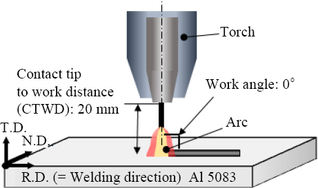
Bead-on-plate welding was performed using an Al 5183 wire with a diameter of 1.2 mm on a 16 mm-thick Al 5083 plate. A VP-GMAW machine (Fronius, Austria) was used and the work angle and the travel angle were set to 0° as shown in Fig. 1. The distance between the contact tip and the workpiece was 20 mm, and Ar gas was supplied with a flow rate of 20 l/min.
Experimental setup
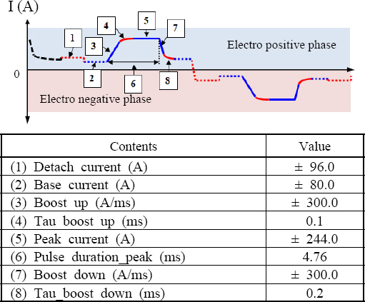
It is advantageous to synchronize waveforms of EP and EN phases for the comparison of the effect of EN pulsing ratio (REN) on bead formation and metallurgical features. As shown in Fig. 2, the waveform of each phase; the current and dwell time were artificially matched to minimize the difference in heat input for each polarity. The duty for phase change also varied depending on the number of pulses of EP and EN in a cycle. In this study, EN pulsing ratio was set to 9 levels and the repetition frequency in a cycle was set to 3 levels. For example, where ratios of EP and EN pulsing in a cycle were 1:3 and 3:9, both have the same EN pulsing ratio of 0.75. However, the phase change frequency is three times higher in the case of 1:3. Table 1 shows the detailed welding condition applied in the experiment.
Schematic diagram of current waveform

Welding conditions applied in the experiment
3. Results and Discussion
3.1 Waveform comparison according to the change of the EN pulsing ratio
The droplets formed during the peak current period (Fig. 2 (6)) were transferred to the molten pool by the push-pull motion of the welding torch during the detach current period. Thus, the number of pulses matched the number of drop transfers regardless of EP or EN phases. Measured waveforms depending on the EN pulsing ratio and the repetition frequency are shown in Fig. 3. Short circuits occurred 13-14 times during 200 ms, which was independent of the EN pulsing ratio and repetition frequency. RMS values of current, voltage and heat input according to the EN pulsing ratio was calculated based on the measured waveforms and are given in Fig. 4. The current/voltage and heat input were similar under the condition when the electrode polarity (EP) having the EN pulsing ratio below 0.5 mainly functions. On the other hand, when the EN pulsing ratio was increased to above 0.5, the total heat input tended to decrease as the current value was decreased. However, the effect of the change in welding speed on the current/voltage and supply energy was not confirmed.
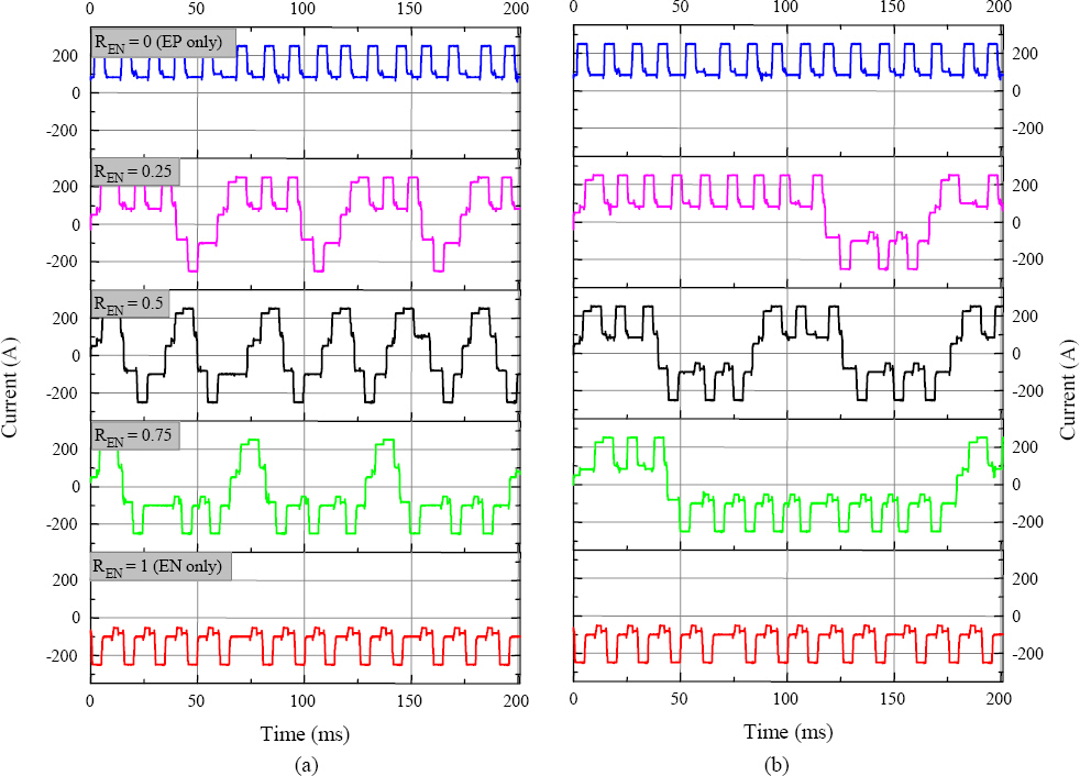
Measured current waveform depending on EN pulsing ratio with (a) one and (b) three times repetition
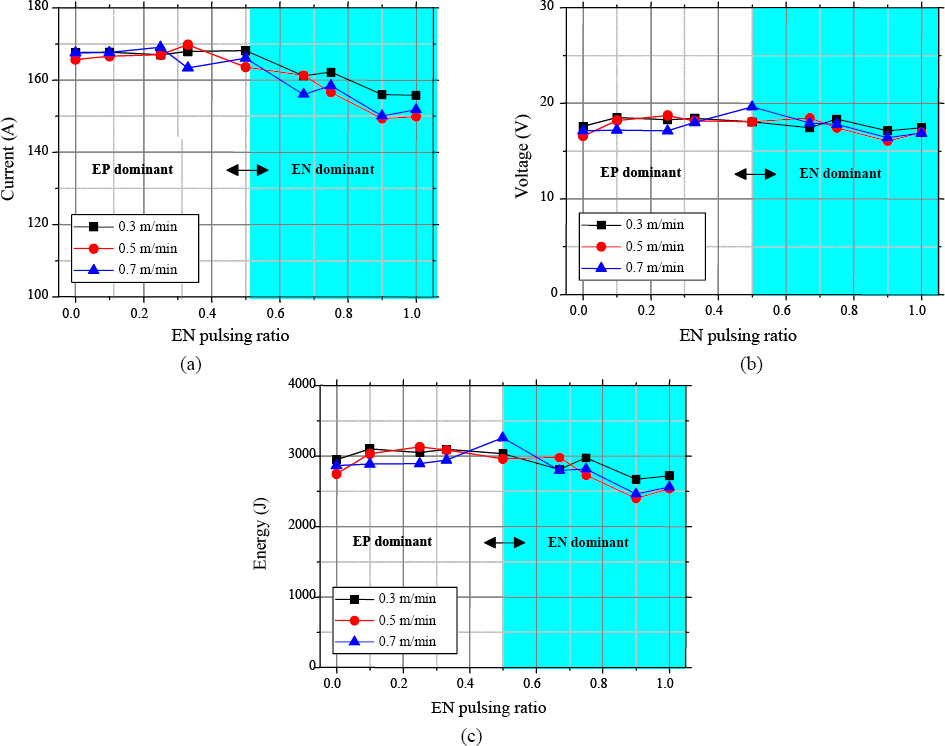
Measured (a) welding current, (b) voltage and calculated (c) heat input depending on EN pulsing ratio and welding speed (one repetition condition)
The droplet size and the molten pool geometry were changed according to the polarity. In Fig. 5, (a)-(c) show the droplet transfer during EP phase, and (d)-(f) show the droplet transfer during EN phase. Fig. 5 (b), (c) and (e), (f) show the droplet transfer behavior at the peak current and detach current period for EP and EN phases, respectively. Deflection on the surface of the molten pool was observed due to arc pressure in the EP phase (Fig. 5(b)), and relatively large droplets were formed in the EN phase condition.
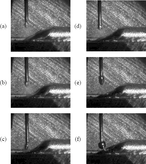
High-speed camera images captured during the droplet transfer depending on phase. ((a) to (c): EP phase, (d) to (e): EN phase). (a) and (d) represent base current period for each phase, (b) and (e) are peak current, (c) and (f) are images for detach current period
3.2 Comparison of weldability according to EN pulsing ratio change
Changes in droplet transfer and surface deflection of molten pool affect the penetration depth and the amount of deposition. Bead appearances according to the EN pulsing ratio were given in Fig. 6. The frequency of phase changes increased until the EN pulsing ratio reached 0.5 and then decreased. Frequent phase changes alleviate the ripples on the weld bead. When the repetition frequency was one as shown in Fig. 6(a)- (e), the ripple was obvious compared to the repetition frequency was 3 or 5 as shown in Fig. 6(f)-(i). As the EN pulsing ratio increased, the height and width of the bead tended to increase. In addition, the height and width of the bead were larger in the low welding speed condition than the high welding speed condition (Fig. 7). Because the increase of the repetition frequency promoted the ripple formation, height and width variations were large in each condition. However, the average height and width of the beads were similar independently of the repetition frequency.

Bead appearances under the variable EN pulsing ratio and repetition. The specimen was fabricated with a welding speed of 0.7 m/min
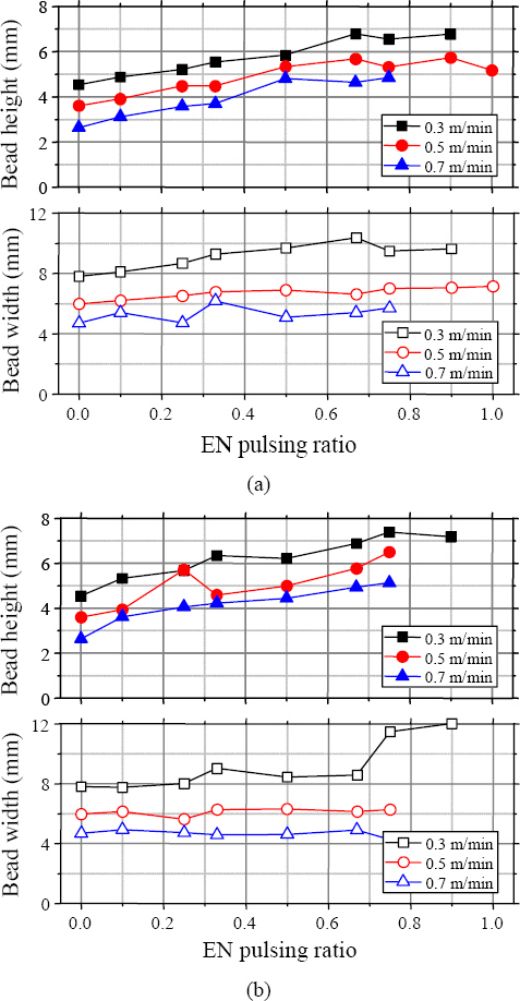
Bead height and width of deposit materials depending on EN pulsing ratio and welding speed under variable repetition conditions of (a) one and (b) five times
The deposited area was increased with increasing EN pulsing ratio in a cycle (Fig. 8(a)). It is considered that the melting of the filler wire was accelerated under the EN phase. On the other hand, the penetration into the substrate was decreased as the EN pulsing ratio increased. In particular, when the EN pulsing ratio exceeded 0.5, penetration decreased rapidly.

(a) Deposition and dilution area derived from sectional image of the welds, and (b) weight of welds per length of 120 mm depending on EN pulsing ratio and repetition.
Because the energy transfer to the substrate was limited, and the effect of gravity during the droplet transfer was reduced by applying the short-circuit transfer process. The weight of the droplets tended to increase proportionally with the EN pulsing ratio and was linearly increased as the repetition frequency increased (Fig. 8(b)). Therefore, it was confirmed that more deposited materials were stacked in the unit weld length at the 0.5 EN pulsing ratio condition where the phase changes frequently. It was predicted as a temporary phenomenon that appeared when the power source controlled the current to stabilize the arc during the polarity change.
3.3 Effects of EN pulsing ratio change on structure formation
The change in EN pulsing ratio affects dilution of the substrate, and the nucleation site may differ due to the flow inside the molten pool by the polarity change14,15). The microstructural constitution of the welds can be varied by numerous factors such as chemical composition, impurities, and welding parameters. The cooling rate is the correlation between the temperature gradient and the solidification rate. It is usually determined by the welding speed and heat input. If the cooling rate is fast, a finer structure can be formed16).
The temperature was measured during the process with a thermocouple attached 11 mm below the upper specimen. As shown in Fig. 9, the maximum temperature and cooling rate were measured at the EN pulsing ratio of 0.5 when the phase change frequency was the highest. The lowest values were obtained when EN or EP polarity was used alone. Even with the same phase change frequency, the measured temperature was different according to the EN pulsing ratio in a cycle. This trend conflicted with the heat input derived from the measured waveforms in Fig. 4. Therefore, it is inferred that the efficiency and function can be different depending on the polarity.

(a) Measured temperature and (b) calculated cooling rate depending on EN pulsing ratio. Welding speed and repetition were fixed at 0.5 m/min and three times, respectively
The change of the microstructure according to the EN pulsing ratio was investigated and presented in Fig. 10. Babu17) mentioned that the polarity change during pulse welding could suppress the grain growth because it affected the flow fluctuation inside the molten pool. When the EN pulsing ratio is between 0 and 0.5, the formation of the equiaxed structure was more dominant than the columnar structure as the EN pulsing ratio increasing. At a low phase change frequency (0-0.25), epitaxial growth, a symbol of anisotropy growth, was observed in the direction of the heat source.
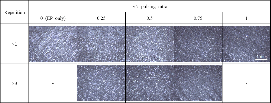
Microstructure in longitudinal direction depending on EN pulsing ratio and repetition
On the other hand, it is presumed that most of the energy was mainly consumed to melt the wire at the EN polarity 100 % condition. Because the droplet tem-perature is lower than the EP phase period, finer grain can be obtained.
4. Conclusion
In this study, the effect of the EN pulsing ratio and the repetition frequency on the bead appearance and microstructure was investigated using a short-circuiting mode VP-GMAW power source and the following conclusions were drawn.
1) EN pulsing ratio change directly affects the arc concentration location, which caused a change in the amount of deposition and melting of the substrate. The droplet size was small, and the surface of the molten pool was deflected due to strong arc generation in the EP phase period. While the droplet size was large even though low input energy was supplied in the EN phase, and the arc was formed at a relatively high position compared to the EP phase period. As the EN pulsing ratio increased, the weight of the deposition tended to increase, and width tended to increase. As the repetition frequency in a cycle was increased, the ripple on the weld bead was clearly observed, but the effect of repetition frequency on the weight of the droplet was negligible.
2) The effect of phase and polarity changing frequency on microstructure formation was confirmed. It is inferred that it is possible to form a fine structure under EN polarity compared to EP polarity. Because not only relatively low heat input was supplied under the condition of high EN pulsing ratio, but also because the temperature of the droplet was low due to the large amount of energy consumed to melt the wire. Epitaxial growth was observed due to the thermal overlap of the applied heat input at a low EN pulsing ratio. It was reconfirmed that anisotropic characteristics can be suppressed through the phase change, similar to the research of Fang11) and Cong12). As the frequency of phase change increased, the size of the grains decreased. When the repetition frequency in a cycle increased, the frequency of phase changes decreased. Thus, it is considered to be advantageous to reduce the repetition frequency to reduce the grain size.
Acknowledgement
This research was carried out with the support of the Korea Institute of Industrial Technology (KITECH) and the National Research Foundation of Korea (NRF) grant (Task No. 2019R1F1A1042353).