A Study on the Change of Wire Feeding Speed in GTA Welding (Ⅰ) - Changes in the Modes of Metal Transfer -
Article information

Abstract
GTA welding (GTAW) is a representative welding technique employed for pipe root gap welding. Although this technique allows the control of the current and wire feeding speed as independent variables, it is difficult to determine these variables to ensure appropriate quality. In the pipe root gap welding task, the parameters of automated welding applications are difficult to determine due to gap and misalignment. Accordingly, this study was conducted to examine changes in the modes of metal transfer according to the welding current and wire feeding speed. In the various processes of GTAW, changes in volume transfer form yield certain advantages and disadvantages, necessitating appropriate tuning procedures to maintain a desired quality. Changes in heat input ratio (HIR), which relates to the welding heat input (HI) and wire feeding speed, were observed to predict modes of metal transfer. According to changes in welding current and wire feeding speed, metal transfer was expressed as an index, and a regression equation was formulated to predict the modes of metal transfer through said index.
1. Introduction
In the ship building process, unit blocks that form the hull are produced through member cutting and such processes as sub-assembly, medium assembly, and large assembly, and pipes with various functions are installed in them. To produce these pipes, filling and finish welding is applied by applying gas tungsten arc welding (GTAW)-based root pass welding and various welding techniques, such as FCAW and GMAW, after the pipe cutting process and clamping process. Many studies have been conducted in industries to apply automation and robots to pipe production in order to improve productivity. It is difficult, however, to apply automation and robot welding due to the gap and misalignment generated during pipe clamping. In addition, applicable equipment is costly, and welding quality is also significantly affected by the clamping condition. Therefore, root pass welding is manually performed in most pipe manufacturing sites, which involves problems, such as securing highly skilled workers, a rise in production costs, and a reduction in industrial competitiveness. M. H. Park et al.1) conducted research on bead geometry prediction in the GTAW underhead position, and M. Navarro et al.2) conducted research on a low-cost AM system based on the GTAW process. J.H Park et al.3-9) expressed plasma stream to improve the filler metal deposition rate based on the GTAW process, and defined the heat input ratio (HIR) by dividing the weld heat input (HI) for the C-type filler metal by the deposition area (DA) as shown in Eq. (1). Experiments of M. Cheepu et al.3) were performed using the C-type filler metal with focus on the depth of penetration (Dp) according to HIR at a welding current of 200A or higher. In this study, however, an experiment was performed at a welding current of 200 A or less using the ∅1.2 wire, which is commonly used in GTA welding, with focus on changes in metal transfer mode. A model was proposed for predicting changes in HIR and metal transfer mode by fixing the welding speed and changing the current (A) and wire feeding speed (WFS).
HIR : Heat input ratio (J/mm3)
HI : Heat input (J/mm)
I : Welding current (A)
E : Welding voltage (V)
U : Welding speed (mm/sec)
DA : Deposition area (mm2)
Wa : Wire section area (mm2)
WFS : Wire feeding speed (mm/sec)
Fig. 1 shows three metal transfer modes and sticking when A is fixed and WFS is increased10,11). (a) is drop transfer. It occurs when HI is significantly larger than the wire melting need energy (WMNE), and melting occurs at the edge of the arc column. (b) is intermittent bridging transfer. When WFS is increased in the state of (a), melting occurs in the center of the arc column due to the increase in WMNE, and the weld metal is supplied to the melt pool intermittently. (c) is continues bridging transfer. When WFS is increased in the state of (b), an appropriate balance between HI and WMNE is reached, and the weld metal is continuously supplied to the melt pool. In the case of (d), when WFS is increased in the state of (c), WMNE becomes larger than HI, thereby causing sticking, a welding defect.
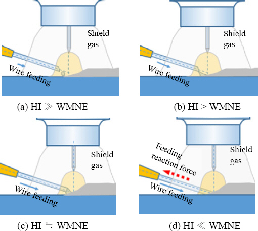
Transfer modes of definition for GTAW. (a) drop transfer (b) intermittent bridging transfer (c) continues bridging transfer (d) sticking (feeding reaction force generation)
2. Experiment
2.1 Materials
In the experiment of this study, SS400 (ASTM A283) with a thickness of 9 mm, a width of 30 mm, and a length of 150 mm was used. In addition, ∅1.2 wire type filler metal was used. Fig. 2 shows the geometry of the base metal while Tables 1 and 2 list the components of the base metal and the chemical components of the filler metal.
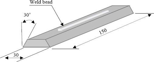
Schematic of base metal

Chemical composition of base metal

Chemical composition of filler metal
2.2 Experimental setup
The experiment was performed using an industrial 6 axis welding robot, a GTAW welding machine, and a wire feeder. Fig. 3 and Fig. 4 show each machine. To secure the reliability of the set and output currents of the welding machine as well as the set and output feeding speeds of the wire feeder, welding was performed by increasing the current from 30 to 200 A by 10 A and the output current was examined using a current meter. To ensure the reliability of the set and output WFS values, the rotation speed was measured using an RPM gauge and the output feeding speed was calculated. It was confirmed that the deviation range was within 95%.
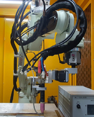
Industrial 6 axis welding robot
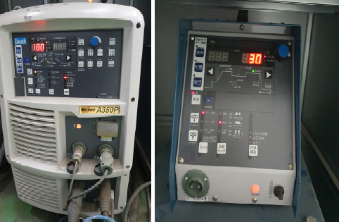
GTA Welding machine and wire feeder
2.3 Experimental conditions
In the experiment, the welding speed was fixed at 15 cpm and the welding current was increased from 100 to 200 A by 25 A (five steps). WFS was increased from 30 to 190 cpm by 20 cpm (nine steps). Sticking occurs as WFS increases according to the set welding current.
Therefore, the experiment was performed until sticking occurred. Table 3 shows the welding conditions.
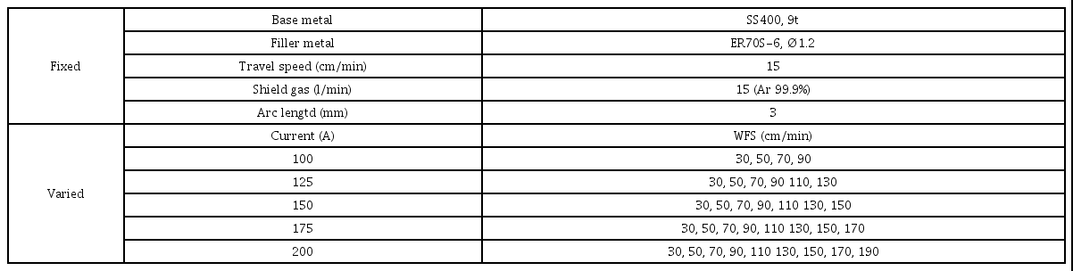
Welding condition of experiment
3. Experiment Results and Discussion
3.1 Experiment results
Fig. 5 shows the relationship between WFS and HIR. It can be seen that HIR decreased as WFS increased at the same current. When the current increased at the same WFS, the metal transfer mode changed in the direction from sticking to drop transfer. When WFS and the current increased simultaneously, there was no change in HIR. It can be seen that the same metal transfer mode occurred at the same HIR. Table 4 shows the metal transfer mode according to HIR by section.

Relation between WFS and Heat input ratio, transfer mode, current (A)

Metal transfer modes according to HIR
Fig. 6 shows the relationship among the current (A), WFS, and metal transfer mode. To set the appropriate welding current and WFS in various GAT welding processes, a regression equation for predicting the index of metal transfer mode (IMTM) with a coefficient of determination of R2=0.9 was proposed as shown in Eq. (4). In the case of IMTM, unlike the prediction of the metal transfer mode according to HIR, a benefit in setting the current and WFS in a production process with a constant welding speed is expected. It is determined that further research is required to secure the reliability of prediction by welding speed.
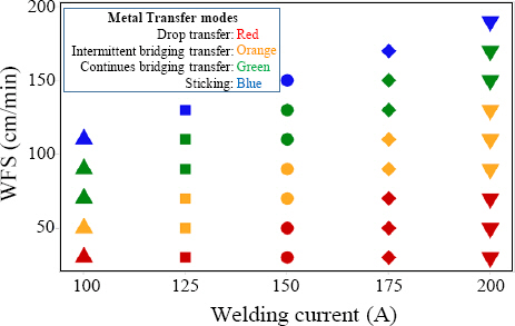
Relation between current (A) and WFS, transfer modes
4. Conclusion
Research was conducted on changes in heat input ratio (HIR) and metal transfer mode according to the welding current (A) and wire feeding speed (WFS), which are independent variables, in gas tungsten arc welding (GTAW).
1) The metal transfer mode was expressed with the weld heat input (HI) and wire melting need energy (WMNE) by fixing the welding speed and current and increasing the wire feeding speed (WFS).
2) The relationship between WFS and HIR was shown, and the change in metal transfer mode according to HIR was presented by section.
3) The change in metal transfer mode according to the welding current (A) and WFS was expressed with the index of metal transfer mode (IMTM). A regression equation for predicting IMTM with a coefficient of determination of R2=0.9 was proposed.
Acknowledgement
This work was supported by Samkun Century Co., Ltd. (welding automation system development to improve the productivity of polyethylene coated steel pipes) through the Korea Institute for Advancement of Technology funded by the Ministry of Trade, Industry and Energy in 2022. (P0020284, innovation support program for small and medium-sized smart shipbuilding in 2022)
- Nomenclature -
WFS: Wire feeding speed (mm/min): Wire feeding speed
HI: Weld heat input (J/mm): Weld heat input
HIR: Heat input ratio (J/mm3): Heat input ratio
WMNE: Wire melting need energy (J/mm): Wire melting need energy