


1. Introduction
In the ship building process, unit blocks that form the hull are produced through processes, such as member cutting, sub-assembly, medium assembly, and large assembly, and pipes with various functions are installed in them. To produce these pipes, filling welding and finish welding are performed by applying gas tungsten arc welding (GTAW)-based root pass welding and various welding techniques, such as FCAW and GMAW, after the pipe cutting and clamping processes. Many studies have been conducted in industries to apply automation and robots to pipe production so as to improve productivity. The application of automation and robot welding, however, is difficult due to the gap and misalignment generated during pipe clamping. In addition, the price of applicable equipment is high, and welding quality is also significantly affected by the clamping condition. Therefore, root pass welding is manually performed in most pipe production sites, and this involves problems, such as securing highly skilled workers, an increase in production cost, and a decrease in industrial competitiveness. Park et al. conducted research on bead shape prediction in the GTAW underhead position1), and Navarro et al. conducted research on a lowcost AM system based on the GTAW process2). Park et al. expressed plasma stream to improve the filler metal deposition rate based on the GTAW process, and defined the heat input ratio (HIR) by dividing the weld heat input (HI) for the C-type filler metal by the deposition area (DA) as shown in Eq. (1)3-9). Cheepu et al. performed experiments3) using the C-type filler metal with focus on the penetration depth (Dp) according to HIR at a welding current of 200 A or higher. In this study, however, an experiment was performed at a welding current of 200 A or less using the Ōłģ1.2 wire, which is commonly used in GTA welding. Changes in bead width (Bw), bead height (Bh), and Dp according to changes in welding current (A), wire feeding speed (WFS), and HIR were observed. Linear regression models were proposed to predict Bw, Bh, and Dp by fixing the welding speed and using A and WFS as variables.
HIR : Heat input ratio (J/mm3)
HI : Heat input (J/mm)
I : Welding current (A)
E : Welding voltage (V)
U : Welding speed (mm/sec)
DA : Deposition area (mm2)
Wa : Wire section area (mm2)
WFS : Wire feeding speed (mm/sec)
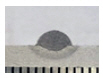
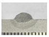
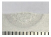
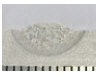
Fig. 1 shows three metal transfer modes and sticking when A is fixed and WFS is increased10-11). (a) is drop transfer and it occurs when HI is significantly larger than the wire melting need energy (WMNE). Melting occurs at the edge of the arc column. (b) is intermittent bridging transfer. When WFS is increased in the state of (a), melting occurs in the center of the arc column due to the increase in WMNE, and the weld metal is supplied to the melt pool intermittently. (c) is continues bridging transfer. When WFS is increased in the state of (b), HI and WMNE are properly balanced, and the weld metal is continuously supplied to the melt pool. In the case of (d), sticking, a welding defect, occurs when WFS is increased in the state of (c) because WMNE becomes larger than HI.
2. Experiment
2.1 Materials and equipment
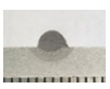
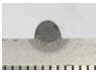
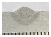
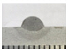
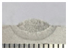
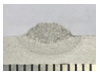
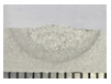
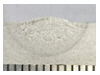
In the experiment of this study, SS400 (ASTM A283) with a thickness of 9 mm, a width of 30 mm, and a length of 150 mm was used along with Ōłģ1.2 wire type filler metal. Fig. 2 shows the geometry of the base metal while Tables 1 and 2 list the components of the base metal and the chemical components of the filler metal.
Fig.┬Ā1
Transfer modes of definition for GTAW. (a) drop transfer (b) intermittent bridging transfer (c) continues bridging transfer (d) sticking (feeding reaction force generation)


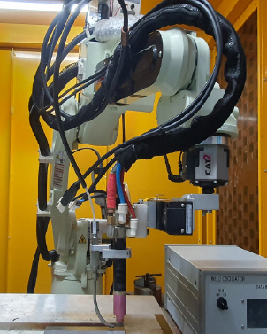
2.2 Experimental setup
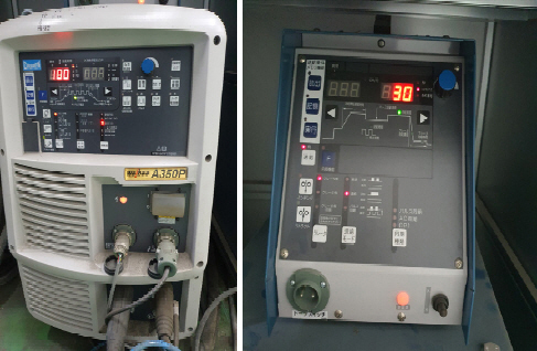
The experiment was performed using an industrial six-axis welding robot, a GTAW welding machine, and a wire feeder. Fig. 3 and Fig. 4 show each machine. To secure the reliability of the set and output currents of the welding machine as well as the set and output feeding speeds of the wire feeder, welding was performed by increasing the current from 30 to 200 A by 10 A and the output current was examined using a current meter. To secure the reliability of the set and output WFS values, the rotation speed was measured using an RPM gauge and the output feeding speed was calculated. It was shown that the deviation range was within 95%.
2.3 Experimental conditions and measurement method
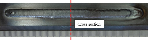
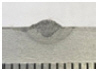
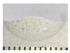
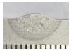
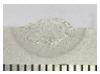
In the experiment, the welding speed was fixed at 15 cpm and the welding current was increased from 100 to 200 A by 25 A (five steps). WFS was increased from 30 to 190 cpm by 20 cpm (nine steps). Sticking occurs as WFS increases according to the set welding current. Therefore, the experiment was performed until sticking occurred. Table 3 shows the welding conditions. Fig. 5 shows the cutting point of the welded bead, and Fig. 6 schematized the measuring point of the welding cross section is schematized.
Table┬Ā3
Welding condition of experiment

2.4 Experiment results
Table 4 shows the macro-section of the weld bead formed by welding except for sticking conditions. When WFS was increased at constant welding current (A), Bh increased while Bw and Dp decreased. When the welding current (A) increased at constant WFS, Bh decreased while Bw and Dp increased.


3. Bead Shape Prediction Model
In the GTAW process, changes in welding current and WFS lead to changes in Bw, Bh, Dp, and metal transfer modes. Various processes that apply GTAW involve text marking welding systems that have Bw and Bh as main management items and processes that require sufficient penetration for complete penetration. In addition, in pipe root gap welding, it is deemed necessary to select an appropriate metal transfer mode. Therefore, in the application of GTAW, models for predicting the bead shape according to the welding current and WFS were proposed. The metal transfer mode according to HIR by section, which was obtained from the study preceding this study12), was applied as shown in Table 5.
Table┬Ā5
Metal transfer modes according to HIR
| HIR (J/mm3) | Metal transfer modes |
|---|---|
| Over 179 | Drop transfer |
| 110~179 | Intermittent bridging transfer |
| 79~110 | Continues bridging transfer |
| 0~79 | Sticking (Feeding reaction force generation) |
3.1 Bead width (Bw) prediction
Fig. 7 shows the relationship among the current, WFS, and Bw.
Bw increased as the welding current increased, and it decreased as WFS increased. Based on the relationship, a bead width (Bw) prediction model with a coefficient of determination of R2=0.97 was proposed as shown in Eq. (4).
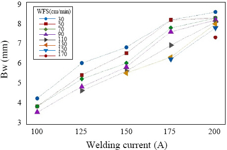
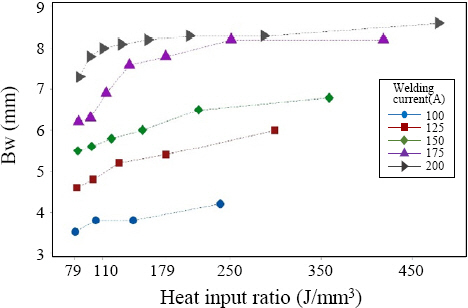
Fig. 8 shows the relationship among HIR, Bw, and the current. Bw significantly changed according to the change in welding current. The change in Bw according to the change in HIR was large in the continues and intermittent bridging transfer sections, but it was small in the drop transfer section.
3.2 Bead height (Bh) prediction
Fig. 9 shows the relationship among the current, WFS, and Bh. Bh decreased as the welding current increased, and it increased as WFS increased. Based on the relationship, a bead height (Bh) prediction model with R2=0.90 was proposed as shown in Eq. (5).
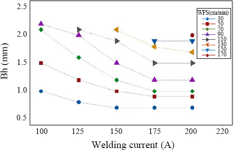
Fig. 10 shows the relationship among HIR, Bh, and the current. The change in Bh according to the change in welding current was not significant, but the change in Bh according to the change in HIR was significant.

3.3 Penetration depth (Dp) prediction
Fig. 11 shows the relationship among the current, WFS, and Dp. Dp increased as the welding current increased, and it increased as WFS increased. Based on the relationship, a penetration depth (Dp) prediction model with R2=0.95 was proposed as shown in Eq. (6).
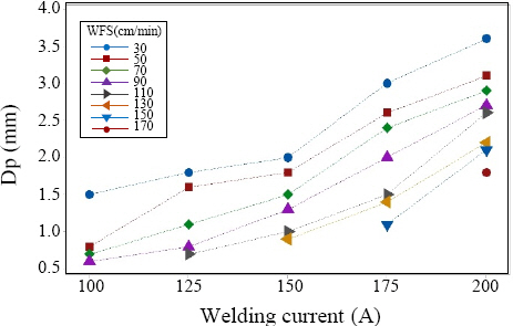
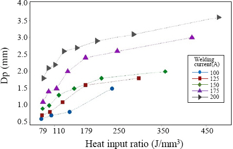
Fig. 12 shows the relationship among HIR, Dp, and the current. The change in Dp according to the change in welding current and HIR was significant.
4. Conclusion
In this study, an experiment was performed by changing the welding current (A) and wire feeding speed (WFS) with the welding speed fixed at 15 cpm to investigate the bead width (Bw), bead height (Bh), and penetration depth (Dp) according to A and WFS as well as the metal transfer mode according to the heat input ratio (HIR) in gas tungsten arc welding (GTAW). The results are as follows.
1)Changes in bead shape according to changes in welding current and WFS were shown in Bw, Bh, and Dp graphs. Linear regression models for predicting Bw,
2)Changes in HIR according to changes in welding current and WFS were shown in Bw, Bh, and Dp graphs. Sections to predict metal transfer modes were presented.
3)In the GTAW process, the prediction of the weld bead shape and the presentation of metal transfer mode sections for setting welding conditions are expected to be significantly helpful in predicting welding quality. Further research is required to improve the reliability of the predictive models by applying the results of this study to butt, root pass, and deposition welding conditions.
 PDF Links
 PubReader
 ePub Link
 Full text via DOI
 Download Citation
 Print
Print