1. Introduction
Underwater welding is a critical engineering method indispensable for ships
1). This is because underwater welding is an essential response measure for emergency repair of commercial ships in operation and warships in action
2).
Moreover, underwater welding is being used in various forms in construction and maintenance of underwater structures for facilities related to the petroleum industry, such as subsea pipelines and offshore platforms
3). In particular, a wide range of research is being conducted on underwater welding techniques applicable to the permanent repair of floating production storage offloadings (FPSOs), which are almost permanently installed at a fixed location at sea, or very large ships with deep draft that cannot be dry docked
4).
According to Korea Occupational Safety and Health Agency (KOSHA), various types of industrial diving are practiced in various depths and environments in South Korea surrounded by the sea on three sides
5). Considering the national environment and industrial conditions, the importance of developing technology and providing sufficient information on underwater welding and cutting is also emphasized for emergency rescue and military operations such as local repair and maintenance of major marine facilities, equipment, and ships, as well as maritime accidents
6).
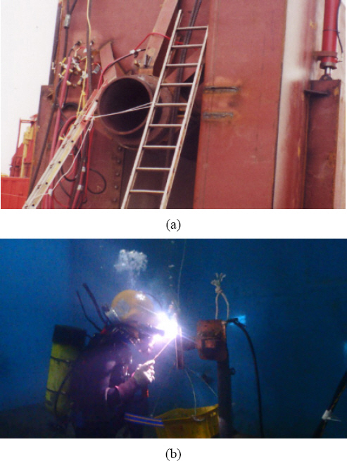
In the U.S., various methods of underwater welding, such as dry habitat welding (
Fig. 1(a)), which guarantees the same welding quality as topside welding, are being used for oil-related facilities such as subsea pipelines in the Gulf of Mexico. Wet shielded metal arc welding, illustrated in
Fig. 1(b), is one of the most familiar methods that is actually applied in many industrial diving sites in South Korea.
Fig.┬Ā1
Underwater welding method, (a) dry welding habitat, (b) wet SMAW
Thus, the use and importance of underwater welding in actual industrial field is being emphasized. However, there is no independent education and qualification system for underwater welding in South Korea. However, they are designated as a part of the underwater performance task during the practical examination for diving industry engineers and diving technicians organized by the Human Resources Development Service of Korea (HRDK). Consequently, domestic divers are required to practice and evaluate underwater welding voluntarily and involuntarily to obtain a national qualification of industrial engineer diver higher.
As mentioned above, despite the fact that domestic underwater welding has a very high importance in the national technical qualification system, there is currently no underwater welding education system, evaluation standards, or research that satisfy international standards.
Therefore, this study measured the problems and constraints of each step of the underwater welding curriculum through educational experiments, and discussed the challenges necessary to educate the students to a level that can be utilized in the actual industrial field.
2. Underwater Wet Welding
2.1 Characteristics of Underwater Wet Welding
There are a few challenges to be overcome for underwater wet welding to achieve the same quality as topside welding.
First of all, the underwater environment limits visibility, and as illustrated in
Fig. 2(a) and
Fig. 2(b), gas bubbles generated during welding obscure the molten pool, i.e., the weld puddle, making it difficult to form the correct bead
7).
Fig.┬Ā2
The over view of underwater wet welding, (a) the arc & gas bubbles, (b) the schematic of underwater wet SMAW
7) 1. water vapor 2. gas bubbles 3. flux coating 4. core wire 5. melting flux coating 6. liquid metal 7. electric arc 8. base materials 9. slag on weld metal 10. gas from melting flux coating
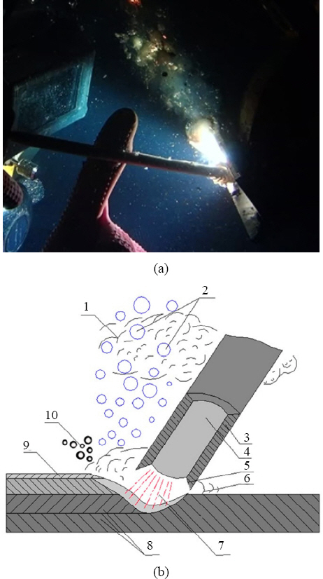
The water surrounding the arc (H
2O) is electrolysed into hydrogen (H) and oxygen (O
2) during welding. During this process, diffusible hydrogen is absorbed, causing hydrogen induced cracking (HIC)
8). Water also causes a quenching effect that cools the base metal and weld metal very rapidly. At this point, the heat affected zone (HAZ) and the weld metal are transformed into a hard martensitic microstructure with different strength and ductility than the base metal, which causes cracks to form
9,10). Thus, various studies have been conducted on temper beads to overcome welding defects caused by microstructure changes in the heat-affected zone due to rapid cooling
11,12).
2.2 Underwater Wet Welding Method
There are two main techniques of underwater welding depending on the welding rod manipulation method and skill level. First, The self-consuming technique consists of keeping the welding rod in contact with the base metal, maintaining a constant work angle and drag angle, and dragging the rod in the direction of the weld according to the weld speed. This is sometimes referred to as the drag technique because the diver does not specifically manipulate the welding rod
13). Hence, this method can be used by less experienced divers and in situations that do not require high weld quality, such as emergency rescue, and is mainly suitable for single-pass welding.
Next, the manipulative technique is mainly used for multi-pass welding and is applied when a more specific quality weld is required, such as increasing the amount of welding by varying the current value between beads, changing the angle of the welding rod, or adjusting the welding speed. It requires a higher skill level than the self-consuming technique
14).
Other methods include weaving, which involves moving the tip of the welding rod from side to side to widen the bead or adjust its thickness; oscillation, which involves moving the weld holder to change the working angle or advance angle to keep the shape of the arc cup constant; and step back, which involves moving the welding rod forward and backward to produce small overlaps of the weld bead to create more welds, similar to the weaving method.
However, unlike topside welding, the above welding methods require special care because of quenching effect due to rapid cooling and slag mixture between beads.
2.3 Underwater Welding Rod
Wet shielded metal arc welding (SMAW) uses specially waterproofed underwater welding rods for actual underwater construction, and for other reasons such as cost, general welding rods are used with a waterproof coating such as paraffin wax
15). E7014 or E6013 welding rods of the rutile series are commonly used for carbon steel, which are known for their excellent arc stability and weldability
16).
Furthermore, even in emergency situations or educational purposes where it is difficult to supply specialized welding rods, waterproofing of welding rods is essential for a certain level of welding quality. In particular, paraffin coating is studied to cause less cracking in hydrogen organic cracks (HIC) and heat-affected zones (HAZ)
17).
2.4 Defections of Underwater Wet Welding
The American Welding SocietyŌĆÖs underwater welding code (AWS D3.6M) is followed for defects in underwater wet welding, and the main visual defects in fillet welding are as follows.
The main defects of underwater wet welding are mostly caused by the inability to form the required weld size, such as weld leg or throat, due to limited visibility caused by chemical gas bubbles generated during welding, in addition to the environmental factor of being underwater.
Undersized welds in the root pass are most often caused by too fast a welding speed or insufficient weld penetration due to an incorrect weld angle, resulting in thin and slender beads.
Due to the nature of underwater wet welding, if the arc length is too long or the welding speed is too fast when using high current values, the weld may deviate from the center of the bead and weld to one side of the base metal. Or it may weld to both sides but not to the center of the bead, resulting in a trem, where the bead splits in two
18). Even if the weld is welded to both sides of the base metal, if the weld layer is too thin, a bead with a concave center is formed. This undersized of weld in the root pass makes it difficult to form a second or third pass later.
In contrast, if the current value is low or the welding speed is too slow, a convex bead is formed with excessive weld concentration in the center of the bead. An overlap occurs if the weld is concentrated on one side of the bead.
The most common visual defects in multiple passes are undersized welds and unplaned weld surfaces in the second and third passes, which result from the failure to correct defects originating in the root pass.
Slag inclusion happens when some of the cladding material residue fails to escape from the fast cooling melt or when weaving is done excessively. Slag inclusion can also be caused by insufficient cleaning between beads during welding and has a significant impact on weld quality.
Other problems include burn through due to high current values in underwater welding, or poor crater or drop-shaped worm holes due to inappropriate current blocking.
Furthermore, during the transfer process, the droplet cannot be welded to the bead and rapidly solidifies, resulting in small drop-shaped spatter of various sizes. This may interfere with the progress of the welding rod if the larger spatter settles on the bead
19).
3. Underwater Welding Education Experiment
3.1 Underwater Welding Tank and Equipment
This underwater welding education experiment was performed in an indoor tank with a 5 m depth shown in
Fig. 3(a).
Fig. 3(b) shows a weld jig with a height of about 1 m and the actual weld depth is 4 m.
The welding base material is a commercially available seamless 6 mm thick mild steel, which is welded to an 80 mm wide and 300 mm long steel plate with a 40 mm wide and 300 mm long steel plate in the form of a T-joint coupon as shown in
Fig. 3(c).
Fig.┬Ā3
The over view of underwater wet welding experiment, (a) welding pool, (b) wet welding preparation in 3F position, (c) T-joint coupon, (d) welding consumables
Fig. 3(d) shows underwater welding rods made of E7014 and E6013 welding rods with a thickness of 3.2 mm, which are available in the domestic market, with a two-layer coating of paraffin wax.
A surface supplied diving system (SSDS), including a Superlite-27 diving helmet, was used, along with a miller 400 DC welder and broco underwater welding holder.
The composition of the underwater welding equipment and welding materials used in this study are summarized in
Table 1.
Table┬Ā1
The equipments used for this study
|
Welding pool (m) |
5(Length) ├Ś 5(Width) ├Ś 5(Depth) |
|
Welding machine |
Miller welding 400 Amp. and Broco underwater welding holder |
|
Diving equip. |
Superlite-27 diving helmet with SSDS |
|
Consumables* (mm) |
E7014 and E6013 3.2(Thickness) ├Ś 350(Length) |
|
Welding coupons (mm) |
6(Thickness) ├Ś 300(Length) ├Ś 80(Width) and 6(Thickness) ├Ś 300(Length) ├Ś 40(Width) |
3.2 Human Resources and Background
A total of 15 volunteers (trainees) participated in this underwater welding education experiment. They were all male students in their early 20s to early 30s who were enrolled in the second year of the Industrial Diving Department at Korea Polytechnic University Gangneung Campus. All participants completed 9 credits in total, including 6 credits for theory and practice of topside welding and 3 credits for theory and practice of underwater welding.
The 3 credits of underwater welding consisted of generating and maintaining an arc underwater, making horizontal and vertical beads on a flat base metal, and making horizontal and vertical beads on a fillet base metal. Thus, they have a basic ability to perform underwater welding.
3.3 Preliminary Evaluation
First, a preliminary evaluation of a single pass weld in the vertical position (3F: vertical down) with the E7014 welding rod on the weldment shown in
Fig. 3(c) was performed for all participants to evaluate the baseline items such as weld leg and throat, bead length and appearance, and other weld defects.
The results of the preliminary evaluation were graded as A, B, or C. They were compared to the final evaluation at the end of the experiment to account for differences in individual performance.
Since there are no underwater welding regulations for a single pass, the root pass criteria in
Table 2 were applied. The welds were graded as A if there were sufficient weld leg, throat, and bead length even with defects, B if there were sufficient bead length even with defects and insufficient weld leg and throat, and C if the bead could not be formed or was of insufficient length.
Table┬Ā2
The welding parameters used for this study
|
Value \ Item |
Root pass |
2nd pass |
3rd pass |
|
Arc current (Amp.) |
165 |
150 |
160 |
|
Work angle (┬░) |
45 |
45~50 |
45~50 |
|
Drag angle (┬░) |
┬▒75 |
┬▒70 |
┬▒75 |
|
Leg/throat size (mm) |
5/3.5 |
8/5.5 |
|
Consumables (EA) |
2.5 |
2 |
2.5 |
3.4 Welding Conditions and Experimental Welding
The current values, welding angles, and target weld leg and throat between beads used in this welding experiment are summarized in
Table 2.
The welding parameters were based on the underwater welding rod manufacturerŌĆÖs specifications and the U.S. Navy underwater welding manual
1,14).
The experimental weld was performed by welding the base metal shown in
Fig. 3(c) with the E6013 welding rod in a vertical position in stages of root pass, 2nd pass, and 3rd pass. Afterward, visual inspection was performed on all weld beads.
1) Root pass
First, single bead was welded per dive for the root pass. 165 amp. was used for this. An average of 2.5 welding rods were used, with a working angle of 45┬░ and a travel angle of ┬▒75┬░. The target weld leg and throat were 5 mm and 3.5 mm, respectively.
2) 2nd pass
The 2nd pass was only performed if the root pass had a good appearance and sufficient weld size. 150 amp. was used for this. An average of two welding rods were used with a working angle of 45~50┬░ and a travel angle of ┬▒70┬░. The target weld leg was 8 mm.
3) 3rd pass
The 3rd pass was done only if the 2nd pass had a good appearance and sufficient weld size. 160 amp. was used for this. An average of 2.5 welding rods were used, with a working angle of 45~50┬░ and a travel angle of ┬▒75┬░. The target weld leg and throat were 8 mm and 5.5 mm, respectively.
3.5 Final Evaluation
For the final evaluation, the base metal in
Fig. 3(c) was welded with the E7014 welding rod in a vertical position with a root pass, a 2nd pass, and a 3rd pass. In addition to visual inspection, bending and macro-etching tests were performed on the best results. The final evaluation was based on the American underwater welding code AWS D3.6 class B, which allows up to 20% of the actual weld leg and throat in the visual inspection and 5% of the surface area in the weld cross-sectional inspection to determine A (pass) and B (fail)
16).
4. Result of Underwater Wet Welding Experiment
4.1 Experiment Result by Diver
In this study, a total of 15 divers (#1~#15) performed 10 to 16 experimental dives (average 14.13 dives) each to examine the main technical problems encountered in the underwater welding curriculum and collect basic data to solve these problems. The results of this experiment are shown in detail in
Table 3 and
Fig. 4~
7. The left side of the table shows the number of weld beads for the root pass, 2nd pass, and 3rd pass for each diver. The right side of the table shows the visual inspection results and destructive test results for the preliminary and final evaluations.
Table┬Ā3
The individual runs of each bead passes and result of T-joint coupon test for 3F position
|
Diver # |
Root pass |
2nd pass |
3rd pass |
Total |
The results of inspection |
|
Initial-test(vis.) single pass |
Final-test(vis.) multi pass |
Macro-etch test |
Bend test |
|
#1 |
10 |
3 |
2 |
15 |
A |
A**
|
Reasonable |
Pass |
|
#2 |
12 |
3 |
1 |
16 |
B |
A**
|
Reasonable |
Pass |
|
#3 |
13 |
2 |
├Ś*
|
15 |
B |
- |
- |
- |
|
#4 |
12 |
3 |
├Ś*
|
15 |
B |
- |
- |
- |
|
#5 |
11 |
3 |
├Ś*
|
14 |
B |
- |
- |
- |
|
#6 |
10 |
3 |
2 |
15 |
A |
A**
|
Reasonable |
Pass |
|
#7 |
10 |
2 |
1 |
13 |
B |
B*
|
- |
- |
|
#8 |
12 |
1 |
1 |
14 |
B |
B*
|
- |
- |
|
#9 |
12 |
2 |
1 |
15 |
C |
B*
|
- |
- |
|
#10 |
13 |
1 |
├Ś*
|
14 |
C
|
- |
- |
- |
|
#11 |
11 |
2 |
1 |
14 |
C |
B*
|
- |
- |
|
#12 |
10 |
4 |
2 |
16 |
A |
A**
|
Reasonable |
Pass |
|
#13 |
13 |
1 |
├Ś*
|
14 |
C |
- |
- |
- |
|
#14 |
10 |
├Ś*
|
- |
10 |
C
|
- |
- |
- |
|
#15 |
8 |
3 |
1 |
12 |
A |
A**
|
Reasonable |
Pass |
|
Average |
11.1 |
2.4 |
1.3 |
14.13 |
- |
- |
- |
- |
Fig.┬Ā4
Common welding defects in root pass, (a) irregular bead(under size), (b) discontinuity(crater), (c) concave, (d) trem, (e) one side(work angle), (f) slag inclusion, (g) unplaned surface, (h) spatter interference
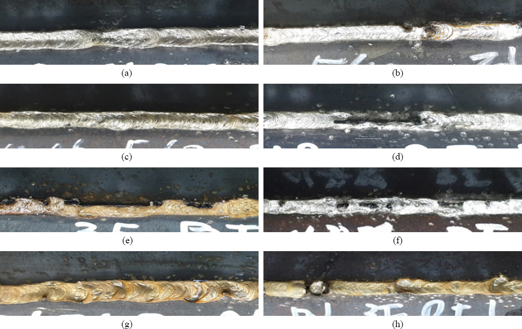
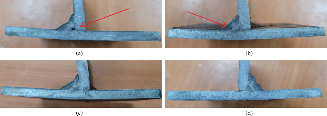
Fig.┬Ā5
Common welding defects in multi pass, (a) insufficient deposit in root and 2nd pass, (b) irregular distance, (c) narrow trench after 2nd pass, (d) overlap, (e) underfill, (f) incomplete fusion, (g) unplaned weld surface(convex beads), (h) unplaned weld surface (undersize)
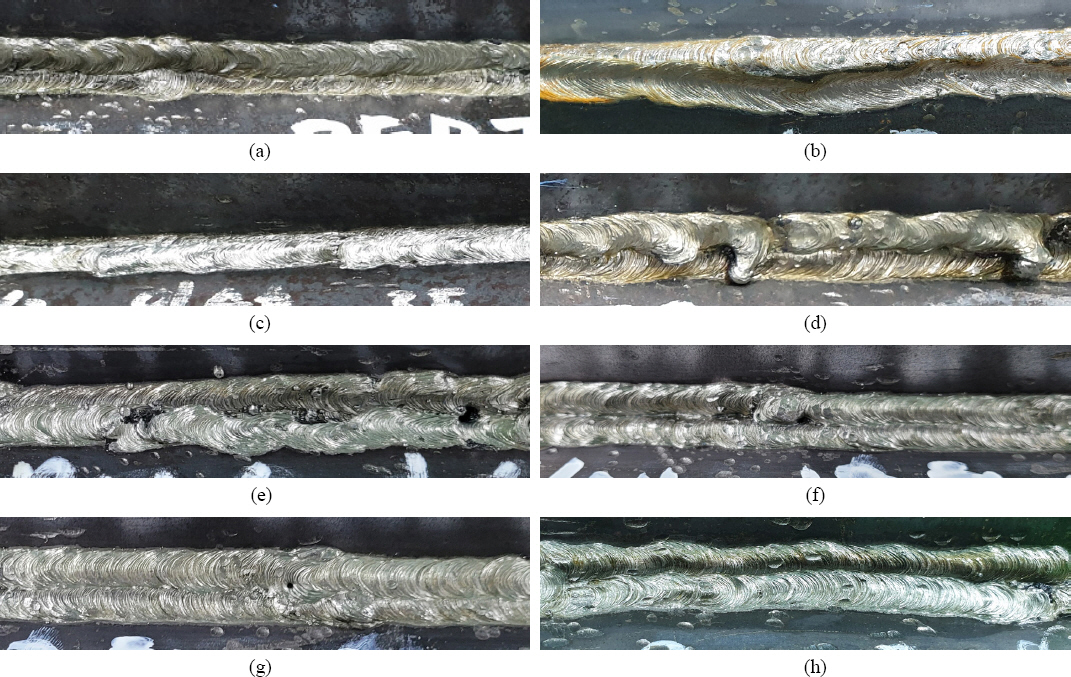
Fig.┬Ā6
The results of bending test, (a) weld face side, (b) back side

Fig.┬Ā7
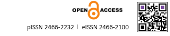
The results of macro etching test, (a) incomplete penetration, (b) slag inclusion, (c) undersize of weld (concave), (d) unplaned weld surface (convex)
The result of each step is as follows.
First, 15 divers performed between 8 and 13 root pass welds (average 11.1) each during the experiment. Among them, 14 divers passed the visual inspection (93%).
Second, 14 divers made between 1 and 4 (average of 2.4) 2nd pass welds during the experiment. Among them, 9 divers passed the visual inspection (64%).
Third, 9 divers performed 1 to 2 (average 1.3) 3rd pass welds each during the experiment. Among them, 5 divers passed the visual inspection and performed bending and etching inspections (55%).
Consequently, the final 5 out of 15 divers met the quality requirements of class B of AWS D3.6 to some extent (33%).
4.2 Result of Underwater Welding Test
4.2.1 Root Pass Defect
The main types of weld defects in the root pass discovered in this study are shown in
Fig. 4.
First,
Fig. 4(a) and
Fig. 4(b) are cases of thin, narrow beads with insufficient weld size to achieve a sufficient weld. In particular,
Fig. 4(b) shows a bead broken by a crater.
Fig. 4(c) is a case of sufficient weld leg but insufficient weld throat, where the weld is not sufficiently centered on the bead.
Fig. 4(d) is a trem where the center of the bead is split in two, and
Fig. 4(e) is a one-sided phenomenon where the weld is only on one side.
Fig. 4(f) corresponds to a combination of slag inclusion and the previous causes.
Fig. 4(g) is a case of unplaned weld surface due to sufficient welding volume but maintain a constant welding speed. Finally,
Fig. 4(h) shows a case where part of the droplet that broke away before it was welded to the base metal, causing cold spatter to stick to the bead and interfere with the weld.
As a consequence, these defects act as major obstacles to the formation of the second and third passes in the future.
However, no convex bead or overlap caused by excessive welding, and no undercut caused by excessive heat concentration were found in the root pass during the underwater welding experiments in this study. Hence, this study focused on selecting the correct amperage, maintaining the working and travel angles, and especially maintaining a moderate welding speed to increase the welding volume.
4.2.2 Defects of the 2nd pass and 3rd pass
The main types of weld defects for the 2nd and 3rd passes in this study are shown in
Fig. 5.
First,
Fig. 5 (a) shows a case where the 2nd pass is welded to the root pass with insufficient weld, and the bead is consistent but insufficient in size, which illustrates the importance of the root pass.
Fig. 5(b) shows a case where the spacing of the 2nd pass is not consistent with the root pass, and
Fig. 5(c) shows a case where the 2nd pass covers the root pass, leaving too narrow a trench for the 3rd pass.
Fig. 5(d) shows a case of excessive welding due to slow welding speed, all of which are obstacles to forming the 3rd pass.
Fig. 5(e) and
Fig. 5(f) show that the 3rd pass did not sufficiently cover the root pass and 2nd pass, or the 3rd pass did not weld properly with the 2nd pass.
Finally,
Fig. 5(g) and
Fig. 5(h) show the unplaned weld surface after the 3rd pass is completed.
Consequently, the poor bead in the 2nd pass, the incomplete deposition and the unplaned welding surface in the 3rd pass are judged to be due to visibility restriction caused by chemical gas bubbles generated during welding. Thus, we focused on overcoming them by such as changing the welding angle.
4.2.3 Defects of Destructive Test
In this study, all of the bending test results were good for example as shown in
Fig. 6 (a) and
Fig. 6 (b), so dose it was not possible to observe the lack of penetration or slag inclusion in the root.
Finally,
Fig. 7 shows the results of the etching test.
Fig. 7 (a) and
Fig. 7 (b) show the results of the etching test, which indicate poor welding at the root and slag inclusion between the beads, respectively. Furthermore,
Fig. 7 (c) and
Fig. 7 (d) both show a insufficient deposition or uneven weld surface. In particular,
Fig. 7 (c) and
Fig. 7 (d) show the welding amount and welding angle between the beads in detail, suggesting the need for further research.
The result of the etching test in this study revealed no defects such as cracks or lack of fusion.
5. Summary and Conclusion
This study examined the main defects of multi-pass welds used in actual underwater welding sites, analyzed their causes and solved them, and discussed effective underwater welding training methods that can be applied to actual industrial sites.
Finally, we summarize the results of the training experiments on single and multi-pass fillet welds for 15 industrial diver trainees who participated in this study as follows.
1) The main visual defects in the root pass were incorrect arc length and welding angle control, and the formation of thin beads and poorly welded beads such as concave beads due to high welding speed. The main visual defects in the 2nd pass were inconsistent spacing with the root pass and the formation of poorly welded beads. The main visual defects in the 3rd pass were lack of fusion between beads and incomplete deposition and unplaned weld surface. Lastly, the main defects in the weld cross sectional inspection were poor penetration of the root pass, slag inclusion, poor weld angle, incomplete deposition and unplaned weld surface.
2) In this study, 14 out of 15 divers passed the visual inspection for the root pass, 9 out of 14 for the second pass, and 5 out of 9 for the third pass. Then bending and etching tests were performed. Finally, 5 out of 15 divers met the quality requirements of AWS D3.6 class B to some extent, with an average of 10 weldments.
3) All four students who received A in the preliminary evaluation passed the final evaluation, while only 1 student who received a B out of 11 students who received B and C in the preliminary evaluation passed the final evaluation, which reflects the difficulty of underwater welding. Most of the students who did not overcome the welding defects in the root pass failed to form a trench in the second pass or to form an even welding surface in the third pass, which illustrates the importance of the root pass in the basic process.
In conclusion, to solve the problem of welding defects in multiple passes, such as incomplete deposition, presented in this study, it appears to be most important to select an appropriate current value between beads, an accurate welding rod angle, and a well-controlled welding speed to ensure sufficient weld. Therefore, the welding parameters in
Table 2 used in this study and the process of performing a series of welds, including weld cross sectional inspection, are considered to be a highly effective and efficient teaching method for fast understanding of the characteristics of underwater welding under limited materials and time conditions.
Finally, the experiments were not conducted to solve the problems presented by the weld sectional inspection results in
Fig. 7 of this study. Further experiments are needed to solve these problems, and it is believed that important basic data necessary for systematic underwater welding education and improvement of underwater welding quality will be accumulated in the process of solving these problems.


 PDF Links
 PubReader
 ePub Link
 Full text via DOI
 Download Citation
 Print
Print