Understanding the Effects of Surface Finish on Diffusion Bonding of AZ31 Alloys
Article information

Abstract
Methods to optimize the diffusion bonding (DB) process while also creating lap joints were investigated using AZ31, the commercial Mg alloy, focusing primarily on studying the effects of varying conventional process parameters and more importantly, exploring the influence of surface roughness on creating an acceptable strong bond. The results indicate that when contact is made between surface areas of roughness (Ra > 0.2 ㎛) diffusion is facilitated at reduced process parameters of time and temperature. Furthermore, this early bond initiation combined with the optimized DB process parameters results in a stronger bond with strengths increasing by ~ 150% in comparison to the DB samples created with a smooth surface finish. Additionally, less than 20% total overall distortion is observed while preserving a uniform microstructure of consistent grain sizes in the material over the entire joining region compared with the parent material.
1. Introduction
Diffusion bonding (DB) is a solid-state material joining process utilizing heat and pressure to facilitate atomic and granular mobility to coalesce the individual sheets of material into a singular solid structure. This method of material joining provides a range of benefits over many of the more traditional forms of joining. One of the major attributes is that DB is performed at temperatures below the melting point of the material and in many instances, below the critical temperatures where materials properties could be negatively impacted1). Because of the preservation of these intrinsic materials properties, the structural integrity of the diffusion bond minimally deviates from that of the bulk material located outside of the optimized zone of influence of the bond2). Having this consistent range of predictable materials properties throughout the bonded area provides an attractive option for many lightweight applications of materials requiring high-strength joints for operation in harsh environments3). Additionally, the uniqueness offered by the DB process not only provides an alternative manufacturing process, but also offers the distinct ability to join materials that are oftentimes impractical or impossible to join otherwise4,5).
Even with the uniqueness and attractive attributes proffered by DB, the process inherently also has its own disadvantages, many of which have hindered full acceptance and widespread use of the process as a primary bonding method in applications where it could confer immense value. These disadvantages include primarily the need for a specialized and expensive DB equipment for achieving and maintaining the exacting process parameters during the entire DB operation1). Other disadvantages include complex sample preparation prior to subjecting the carefully prepared sample to the DB equipment. This complexity includes creation of an optimal surface polish devoid of any contaminants to achieve intimate contact between the bonding materials. Preparation of the sample is typically a rigorous and time-consuming process. Once this ideal sample preparation is obtained and the sample is orientated for DB, the environment required to facilitate the bonding processes typically results in high levels of geometric distortion in the sample. These distortions if not contained renders it difficult to preserve dimensional tolerances and the desired detailed features in the final construct3). Additionally, the distortion presents other disadvantages directly affecting the quality of the bond by relaxing the imperative contact between the sheets limiting the efficiency of bonding. To help mitigate many of these issues, it is common practice to employ supplementary and highly specialized equipment, adding yet another level of complexity and moreover, adding to the cost of the overall process.
While all the above-mentioned aspects convolute the DB process and diminish its attractiveness for use in many applications, it is the aim of this effort to reverse that consensus by understanding and mitigating the geometric distortions within the commercial lightweight magnesium (Mg) alloy, AZ31. Somekawa et al.6) first studied DB of AZ31 and reported on the superplastic characteristics and diffusion bonding behavior of the alloy sheets having equiaxed grain size of ~17 microns. They reported DB of the alloy which was executed in the temperature range of 350°C to 450°C wherein they observed that the alloy was successfully diffusion bonded at the superplastic temperature by selection of suitable combination of pressure and time. Prior to DB, they sandblasted the bonding surfaces using a 20 microns diameter alumina grit for 60 seconds, employing a blasting pressure of ~0.2 MPa. They reported that these were the surface conditions that resulted in the most preferred, uniform roughness of ~24.9 microns. The surfaces were then subsequently cleaned in ethanol using an ultrasonic vibration cleaner prior to subjecting the AZ31 alloy surfaces to DB at bonding pressures of 1 to 10 MPa and with bonding times up to 8 h in air. They reported extensively on the influence of DB parameters of temperature and pressure on the closure of voids to achieve high-quality joints and compared their results with predicted models of Chen-Argon and Pilling-Ridely. They observed reduction in the diffusion bonding times than those predicted by the models, and they assumed the difference to be due to the rugged surface conditions created by sandblasting. They reported that the surface roughness of ~24.9 microns used in their work was rougher than those reported in the literature6) which are typically < 15 microns. A lower surface roughness typically favors diffusional flow process which leads to void closure. However, when the initial bonded surface is much rougher and greater than 15 microns, then the hypothesis is that in addition to diffusional flow there is also different void shrinkage processes occurring which is much faster than the diffusional flow process. Somekawa et al.6) however, did not elaborate on the influence of surface roughness on the diffusion bonding process parameters. The focus of this paper is therefore, to build further upon these initial observations of surface roughness influence on the quality of diffusion bonding and the bond strength outlined by Somekawa et al.6) and delve more deeply into assessing the influence of surface roughness, temperature and pressure on the DB quality, bonding strength as well as attempt to draw a more definitive analysis of the combined influence of these parameters on minimizing and eliminating any morphological and macroscopic distortions in the geometry of the resultant samples. To accomplish this aim, sheets of AZ31 were systematically subjected to a plethora of DB parameters, surface preparations, and bonding environments. Upon completion of these trials, all the parameter sets capable of producing a joint meeting the desired constraints of minimal distortion while preserving bonding strengths were mechanically tested and quantified, offering insight into the most optimal bonding method thus, building upon the AZ31 DB work reported by Somekawa et al.6). Results of these studies are detailed in the following sections.
2. Experimental Procedure
2.1 Sample Preparation
Sheets of the commercially obtained Mg alloy AZ31 (3% Aluminum and 1% Zinc) (Alfa Aesar) were prepared by cutting them into strips (10×50×1 mm). The initial inspection of the material showed elongated grains, thus to revive and restore the microstructure, an annealing treatment (300°C for a time of 120 min.) was conducted to gain a more equiaxed grain size range of 15-30 ㎛7). The initial oxide, a major deterrent in bonding and sintering of Mg alloys was removed from the surface of the AZ31 alloy by hand using silicon carbide metallographic sanding papers (Allied) with the first step using a media size of P180 (180 grit) and the second step of P280 (240 grit). The samples were then ultrasonically cleaned in an acetone bath for 60 min. at room temperature (Branson CPX5800H) and stored in acetone for the remainder of the sample preparation procedure.
Before initiating the DB process, the final surface finish was applied to the mating surfaces on each sheet with the second round of sanding/polishing using the silicon carbide metallographic grinding paper starting at P180 (180 grit) and working to the desired surface finish determined by surface profilometer (profilometer -Federal Pocket Surf EMD-1500). Upon completion of the final surface finishing step, the samples were then again ultrasonically cleaned and assembled into the DB stainless steel compression tooling (allowing a 10 mm overlap between the two sheets designated as the bonding area). From the final round of surface finishing until the sample was placed into the DB press, the samples were kept submerged in acetone or wetted with acetone to limit the formation of any surface oxides or the inclusion of other contaminants which could affect the quality of the diffusion bond.
2.2 DB Bonding process
The stainless-steel compression tooling containing the commercially obtained AZ31 sample (referred to as the “stack”), was placed into the preheated DB furnace (PNK Labs, custom built) to initiate the process (Fig. 1). The process pressure was applied to the stack via a hydraulic ram (initially set by pressure and then locked into position control upon reaching thermal steady state), and the system was allowed to reach its desired temperature void of any atmospheric controls before the start of the process timer (early DB testing used an inert gas flow of argon gas around the samples serving as a shielding gas, which however, failed to result in any observable benefits on the strength of the bond, and thus, it was removed from the process for the remainder of the testing described in this effort). To verify and monitor the temperature throughout the process, several K-type thermocouples (Omega Engineering) were installed into the stack to monitor the temperature in the samples. These thermocouples also controlled the output of the furnace to achieve automatic temperature control with the furnace with an accuracy of +/– 2.5°C. Upon completion of the DB process, the stack was removed from the furnace and immediately broken down to remove the AZ31 samples from the stainless-steel jig. This final step of immediate removal of the sample was performed to prevent any accumulation of additional heat energy stored within the jig from being transferred to the sample leading to continued diffusional flow processes from occurring within the sample.
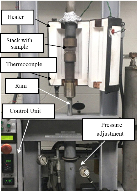
The Diffusion Bonding apparatus was custom built to provide the needed process controls and data acquisition instrumentation for the AZ31 DB samples reported herein. Within the opened heater, between the rams is located the stack containing a sample prior to undergoing DB with thermocouples installed
2.3 Investigatory process and additional trials
The diffusional bonding study detailed here involved two phases, namely, Phase 1 and Phase 2. The objective of the initial “Phase 1” samples stage to define a bonding window comprising a condensed set of processing parameters resulting in minimal deformation and adequate bonding allowing for the initiation of “Phase 2” studies to focus on these parameters thereby enabling a more in-depth study of the bond. To accomplish this, the Phase 1 samples were created by combining all the process parameters comprising 7 different temperatures (400, 425, 450, 475, 500, 525, 550°C), 6 different pressure settings (2.4, 7.2, 12.1, 16.9, 21.7, 26.5 MPa), 6 different settings of time (0.5, 1, 2, 4, 6, 8 h), and finally, 6 different surface roughness conditions (as received, 0.1, 0.12, 0.2, 0.38, 0.78 ㎛). Upon the creation of the various 7×6×6×6=1, 512 combinations set of samples, they were subjected to a manual pull test and visual inspection using a pass/fail distortion gauge to eliminate the samples that had any undesirable characteristics. The pull test incorporated applying a 10N load, located slightly skewed of the long central axis (placing the bond in shear with the addition of a slight torque) to quickly define any weakly bonded samples via sheet delamination. The pass/fail distortion gauge implemented for this initial determination is shown in Fig. 2. The distortion was defined as an increase of 20% of the pre-DB sample measurements (i.e., failure ≥12×60 mm) wherein the samples that contacted the limit markers of the gauge were deemed unacceptable and rejected.
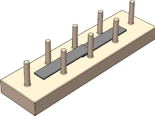
A CAD rendering of the distortion gauge for grading the Phase 1 DB samples. A bonded sample (shown in gray) is placed between the pegs as depicted. If the sample had gained any geometric distortion in excess of 20 percent or greater, interference with the pegs would prevent the sample from easily fitting into the distortion gauge and rate the sample as a failure
Phase 1 was accordingly performed by having three samples for each of the defined set of parameters. Thus, for a group to be rejected all the samples contained within that set were required to fail the pull test or distortion test. If any sample passed regardless of the remaining samples in the group, the group was considered to meet the pass standard criterion. This condensed list of passing criteria determined from the combination of the 1, 512 samples included the temperature values of 450, 475, and 500°C, pressure values of 7.2, 12.1, and 16.9 MPa, time frames of 1, 2, and 4 h, along with the surface roughness values of 0.2, 0.38, and 0.78 ㎛, all of which were then used to create the samples for Phase 2. A notable change from the processes carried out in Phase 1 was the use of thicker sheets of AZ31 (5 mm versus 1 mm) however, keeping all the other dimensions identical, i.e., 10×50×5 mm. This change was implemented to permit the Phase 2 samples to undergo quantitative lap shear mechanical testing. All the remaining preparation and handling steps defined for creating the Phase 1 samples were kept identical and were reproduced accordingly, to create the Phase 2 samples to ensure uniformity.
The Phase 2 samples, once created, were also subjected to the same initial pull and distortion check that was used in Phase 1 with the samples meeting the pass standard criterion. All the samples that passed this visual inspection and screening for distortion and pull test were then further precision sized utilizing a Computer Numerical Control (CNC) milling center. This resizing was performed primarily to remove areas of inconsistent pressure applications near the edge of the sample caused by inadequate contact with the compression tooling while also correctly sizing the samples for the lap shear mechanical testing. The now equally sized samples were then used to provide adequate comparisons of the bond strength (speed - 2.54 mm/min; load frame - Instron; extensometer -Instron 2630 Series; Software-Bluehill 3 Testing Software for Mechanical Testing Systems). Additionally, electron microscopy was also performed to provide a proper correlation of the mechanical strength and microstructure from the tested specimens (FESEM- ThermoFisher Apreo; EDAX - Ametek APEX, 0.1 ㎛ pixel resolution).
3. Results
The Phase 1 results are represented in Fig. 3 depicting a zone of DB parameters (temperatures and pressures) meeting the requirements of surviving the initial pull test while exhibiting minimal geometric distortions (results of the samples that passed the visual distortion and the pull test explained above) are illustrated as darkened diamond shapes). The DB processing time however, did not differentiate the results within any of the subset groupings shown. All the sample sets that were created with less than one hour of processing time failed to bond while the sample sets receiving over four hours of DB conditions exhibited extreme distortion, well over the defined limit. Most of the samples that yielded favorable results were created within the two- hour window except for one set of samples defined by minimal process values (450°C and 12.1 MPa), which required 4 hours to produce acceptable results.

The results of Phase 1 illustrating a bonding window defined by the DB temperature and pressure values. The samples depicted with the darkened diamond shapes exhibited minimal distortion and supported a bonded lap joint between the two sheets of AZ31. Samples represented with an “X” failed to bond whereas the samples represented with a circle provided a large amount of distortion
The results displayed in Fig. 3 were then further characterized by the level of surface roughness and the collective effects are shown in Fig. 4. The data plotted in Fig. 4 correlating the surface roughness with the DB parameters clearly depicts an important relationship relating the increase in sample mating surface roughness with a reduction in the DB processing parameters of pressure and temperature required to create an acceptable and stable bond as depicted by the lap shear mechanical tests displayed in Fig. 5. These collective results accordingly, were used to define the narrow range of parameters employed for DB in Phase 2 for allowing a quantitative ranking supported by mechanical testing results amongst the various DB processing parameter combinations which are shown in Fig. 5. The results gained by the lap shear mechanical testing provide further insight into the DB processes parameters correlating the surface finish, with the overall strength of the joint. Additionally, an in-depth assessment of the fractured surface morphologies depicted in Fig. 6 and Fig. 7 provided by the mechanical testing yielded a further level of visual insight into the quality of the bond and the locations of the oxide fragments of Mg, the presence of which on Mg surfaces clearly limit diffusion of Mg precluding an effective bonding of the surfaces of the Mg sheets.

The bonding window initially depicted in Fig. 3 additionally sorted with regards to the surface roughness of the contacting area of AZ31. From the smoothest surface (Ra 0.12 ㎛) illustrated by circles to the roughest surface (Ra 0.78 ㎛) depicted by diamonds, it can be seen that the DB process values of temperature and pressure required to create the joint were reduced. This reduction in process parameters supports an earlier material diffusion initiation allowing for an increase in bond efficiency as compared to a bond created with smoother surface mating contacts
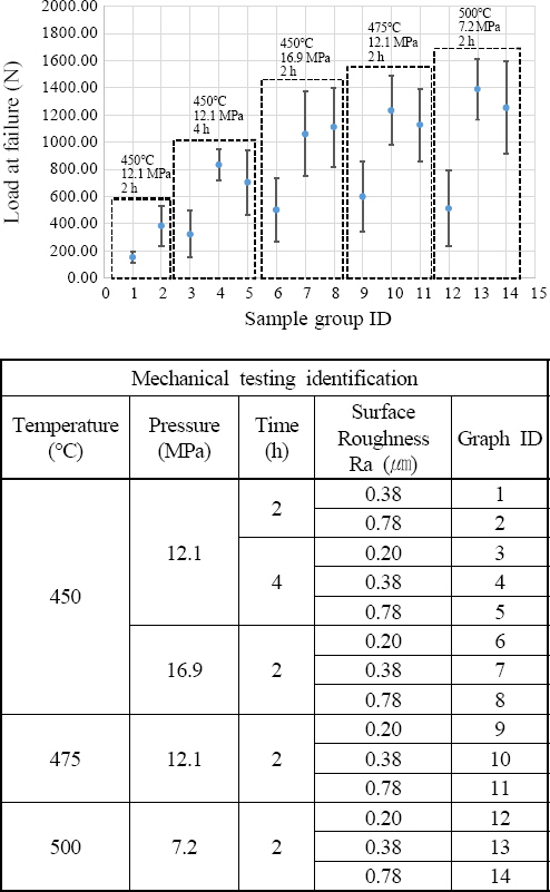
The results of the lap shear mechanical testing conducted on the Phase 2 DB samples. In each subgroup, the rougher surface offered a better bond. Interestingly, the two roughest surface finishes (Ra 0.38 and 0.78 ㎛) equated to indistinguishable values. This observation may support the grain exchange theory, or an additional limiting factor not expressed within this study 15,16). For a comparison to other joining methods such as the spotwelding of a similar joint having a 25×25 contact area, a 6 kN force was rendered at failure alluding to additional optimizations which could be gained17)
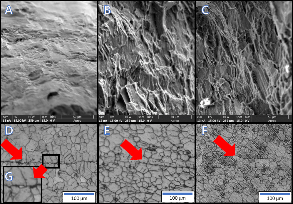
Fractography of the samples post lap shear mechanical testing highlighting the regions of failure with a correlation to the cross-sectional view of the joint directly below. 6A depicts Sample ID #12 with Ra 0.20 µm and 6D showing a well-defined region of the joint after the DB process (arrow). 6B depicts Sample ID #13 with Ra 0.38 µm with 6E showing common grain growth crossing the joint (arrow). 6C depicts Sample ID #14 with Ra 0.78 µm having the joint viewed in 6F mostly faded with only minor areas of non-diffused material (arrow). The topographical features shown in 6A-C indicate remnants of the inter-sheet DB material that created the bond. The higher concentrations of these contact area regions within 6B and 6C clearly support the hypothesis that creation of a rougher surface finish results in a stronger diffusion bond. The smoother surface shown in 6A corelating to a weaker bond is supported with the larger joint and several discontinuities similar to the one shown in the enlarged area in the inset, 6G
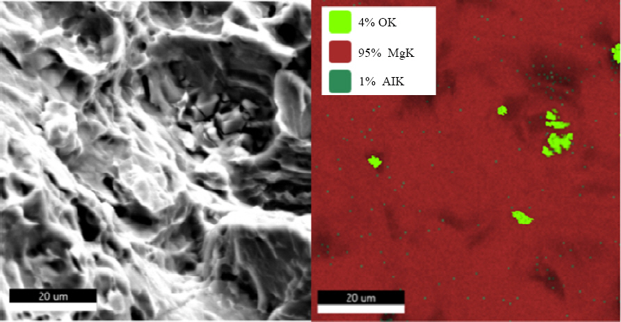
SEM based Energy Dispersive X-ray (EDX) mapping of the fractured area from sample ID#14 following lap shear mechanical testing showing the location of the oxide fragments being primary condensed within the voids. This observation provides evidence of large connate contact areas in commercial AZ31 providing optimal conditions for inducing DB, possibly aided by the fracturing of the surface oxide during the initial contact of the two roughed surfaces and following subsequent onset of induction of localized material flow depositing these fragments in discrete locations, while enabling an acceptable strong diffusion bond
4. Discussion
The results obtained from this research using commercially obtained AZ31 Mg alloy build upon the initial study of Somekawa et al.6) while supporting the results from Zuruzi et al. in a similar study albeit utilizing the aluminum alloy 60618). In both efforts, the noteworthy result was that the creation of a rougher surface finish equated to the realization and formation of a stronger and strong bond. These results are, however, a major departure from the common notion prevalent in DB surface preparation practices wherein a micron smooth, mirror-like surface finish is absolutely warranted and desired to reduce the presence and prevalence of inclusions and voids within the bonding zone causing an effective and strong bond with the desired diffusion, flow and closure of voids1,9,10). For the specific commercial AZ31 alloy studied in this work, what is surprisingly observed by us is that the sought-after reduction of the inconsistencies was essentially aided by the incorporation of additional surface inconsistencies because of the increase in surface roughness. Thus, increasing the surface roughness allowed for a higher bonding efficiency through the creation of favorable conditions for unobstructed atomic migration and diffusion promoting the formation of common grains between the individual sheets thus, enabling and realizing a strong bond11).
The rougher mating surface was, however, only one of the components of the process. The creation of a rough surface finish is also subsequently, additionally aided by the thermal energy and the applied force during the DB procedure that together consequently, overcomes the minor obstructions between the mating surfaces by locally yielding and deforming the mating material12). Evidence of the dependency on this thermal energy relationship supplying the added energy to traverse these minor inconsistencies is observed in Fig. 3. The samples created at 400°C failed to offer an acceptable bond regardless of the increasing value of the applied pressure, yet the samples held at the lowest pressure (2.4 MPa) were able to yield a bond once the process temperature increased beyond 550°C. Even though bonding was possible at these elevated temperatures, it should be noted however, that the samples exhibited immense levels of geometric distortion. Thus, it is critical to note the importance of defining the bonding window wherein an appropriate balance between the joint strength achieved by the diffusion bond and accompanying possible distortion with excessive implementation of the diffusion bonding parameters of temperature, pressure and time both need to be optimized employing a suitable temperature and pressure settings of the diffusion bonding setup.
Defining this bonding window using the temperature and pressure mapping is common within the DB field and is thus, very well known. However, an additional parameter of surface roughness was identified in this study to significantly impact the quality of the DB process for joining the specific commercial AZ31 alloy samples considered in this study. The data shown in Fig. 4, illustrates that a stronger bond is linked to a non-optimal, rough surface preparation (Ra of 0.12 versus 0.78 ㎛). Use of these parameters with reduced thermal energy still results in a bond while minimizing thermally linked geometric distortions. The results depicted in Fig. 5 also clearly shows that the strength of the bonds created from a rougher surface finish outperformed the conventionally prepared smooth surface (please see groups 3, 6, 9, and 12 with a surface roughness of 0.2 microns within Fig. 5, compared to the rougher surface finish created on the other samples). The micrographs shown in Fig. 6 also further supported these results while also providing possible insight into this counterintuitive surface roughness/DB relationships. Within these images it should be noted that, the topographical features clearly show higher concentrations of the bonded regions across the contours of the surfaces of the samples having a rougher surface finish of 0.38 microns and 0.78 microns, respectively. These regions clearly depict locations of yielded material which was once part of the common material bonding the individual sheets (see Fig. 6 B and Fig. 6 C equating to the surface roughness values of Ra 0.38 and 0.78 ㎛, respectively compared to Fig. 6 A corresponding to the surface roughness of Ra 0.20 ㎛). These higher concentrations of the diffusion bonded samples sharing the material bridges are predominately found on the cross- sections of the roughly prepared surfaces. These results therefore depict the favorable attributes of a rougher surface leading to acceptable diffusion bonded sheets at reduced DB parameters. Further optimizations identifying the optimal surface conditions supporting the increased rate of material diffusion thereby resulting in a stronger diffusion bond are however, clearly warranted and are part of the future studies.
For optimal diffusion conditions, as is noted from the current study, it is not the smoothest surface, but the surface offering the most intimate contact afforded between the tip of the roughened peaks of two contacting surfaces that results in an acceptable strong bond. When investigating the minimal contacts offered by the rough surface finish and viewing the process in a static fashion, it may be perceived that this minimal contact is a disadvantage. However, it should be noted that once the process is viewed dynamically, the initial minimal contacts quickly transcend into the initial pressure application points which serve to initiate and promote rapid diffusion and material flow of the Mg atoms thus, resulting in a strong bond. This concentration of forces also causes the applied forces to induce yielding of the AZ31 alloy thereby resulting in localized plastic deformation around those contacting areas similar to what was observed and reported by Somekawa et al.6) and others13,14). The resulting homogenous material flow hypothesized from this deformation zone initiated by the contact points of higher surface roughness regions possibly mimics the flow of a DB process wherein an interlayer of different material is heated to near liquidus temperature that flows into the asperities of the materials to be bonded, creating a near perfect surface contact within the interface14). The resulting localized flow of the alloyed Mg atoms in AZ31 thus creates this intimate contact between the induvial sheets which additionally serves in a favorable way to also fracture the brittle surface oxide, a major deterrent perceived in the sintering and fusion of Mg alloys, adding to the creation of an even more innate and intimate material contact between the metal surfaces (Fig. 7). Once there is enough surface contact created to support the applied pressure, the yielding of the material ceases and the contacting surfaces continue to enable diffusional flow of material accompanied with concomitant grain growth and creation of uniform microstructure thus, resulting in favored joining of the material surfaces for the remainder of the timed processes12). It should be noted from the results shown in Fig. 5 that in each subgroup, the rougher surface offered a better bond. However, interestingly enough, the two roughest surface finishes (Ra 0.38 and 0.78 microns) equated to indistinguishable values. This observation we believe may support the grain exchange theory, an additional limiting factor that is not expressed or considered in this study15,16). This will be engaged in a future study. Furthermore, it is worth mentioning that other joining methods such as spot welding of a similar joint having a 25×25 contact area, a 6kN force was realized at failure17). In comparison, our DB joints realize ~1.4kN. The focus of the present study is to demonstrate the effect of surface roughness on achieving an acceptable bond with minimal deformation. The DB process parameters were not optimized for achieving maximum strength. This is also part of the ongoing future research effort.
Exploring the early and localized plastic flow aided by the application of a concentrated force, an additional set of samples were prepared and subjected to an early and quick application of force. For this setup, an initial pressure of 12.1 MPa was applied until the temperature in the sample reached 475°C at which time the pressure and contact with the hydraulic rams were removed from the sample. After 120 min. of being subjected to this temperature, the samples were removed and subjected to the 10N initial pull test and distortion measurements. The smoothest surface finish of Ra 0.12 microns failed to bond and fell apart upon stack disassembly. On the other hand, the sample exhibiting a surface finish of a Ra value of 0.20 ㎛ failed the initial pull test as the two bonded surfaces delaminated. However, both roughly prepared surface finished samples of Ra of 0.38 and 0.78 ㎛ maintained the integrity of the bond during the initial pull test. Additionally, all the samples subjected to this microcosm of testing received minimal distortion, much less than the defined 20 percent used as the threshold in this research thus, providing possible insights into the benefits of removing the applied pressure after its initial application. These samples were, however, not mechanically tested, and thus only nonquantitative perceived results are presented here at this time. This experiment was nevertheless, initiated to validate the observations documented in this work and indeed these results are clearly in agreement with the data depicted in Fig. 4 and Fig. 5. Additional studies executed in this area to be conducted as part of the future work, with further optimizations as mentioned above, along with studying the influences of incipient and local plastic flow by application of concentrated forces, which may all prove to be extremely valuable and insightful.
5. Conclusions
The results of this effort provide insights into the DB of commercial AZ31a alloy and the effects of using differing surface roughness on the bonding surfaces. It was observed that a sample receiving a rougher surface preparation performed more favorably within the diffusion bonding process parameters than the sample exhibiting a much smoother surface finish following a tedious and exacting polish. The benefits gained from this rougher surface finish of Ra of 0.38 microns and 0.78 microns include a reduction in overall sample distortion, an increase in the strength of the bond, and a much simpler method to prepare the samples prior to bonding. Furthermore, the simplistic preparation process in conjunction with this work being performed in air and not requiring any sophisticated fixation equipment, offers a remarkable increase in the overall process efficiency while also reducing the required processing time, temperature, and pressure for achieving an acceptable strong bond. These aspects thus, increase the attractiveness of the applicability of DB particularly, for lightweight metals such as Mg and Mg alloys while promoting its applications to many other metallic alloy systems moving into the future with a reduction in the precision of the process parameters required. Additional studies conducted to gain a deeper understanding of the early initiation of the localized yielding of the atoms within the material and a detailed investigation of the correlation of the surface roughness to bond efficiency in other materials, will greatly benefit and provide further valuable insights into the understanding of DB as a viable bonding and joining option for various metallic systems. These studies will be initiated as part of the ongoing future plans.
Acknowledgements
The authors would like to acknowledge the support of the U.S. National Science Foundation funded Engineering Research Center - Revolutionizing Metallic Biomaterials (ERC-RMB), Grant #EEC-0812348 for partial support of this research. Prashant N. Kumta (PNK) also kindly recognizes the award and receipt of the Edward R. Weidlein Endowed Chair Professorship funds. The Center for Complex Engineered Multifunctional Materials (CCEMM), Swanson School of Engineering at the University of Pittsburgh is also graciously thanked for providing the required facilities, equipment, and the necessary organizational infrastructure required to execute and complete all of the work outlined and detailed in this manuscript.
Data Availability
All data related to this work cannot be shared at this time as the data also forms part of an ongoing study. However, the authors will be glad to share the relevant information upon reasonable request.