


1. Introduction
Recently, shipping companies are showing changes in placing orders for eco-friendly energy fuel systems along with the enlargement of shipping capacity. IMO (International Maritime Organization) is implementing various regulatory measures to reduce the share of greenhouse gas reduction by 50% compared to 2008 by 2050. Accordingly, shipping companies are considering using minimized carbon or carbon zero fuel1). In the production process, many studies have been conducted to prioritize the shaft centering work in order to shorten the construction period. As the development of design and FEA (Finite Element Analysis)-technology about structural strength progresses rapidly, the use rate of high-strength steel with high yield stress is increasing. These changes have caused the structural rigidity of the hull to be lower than before, and face the possibility of deformation more easily with respect to external loads. However, the rigidity of the propulsion shaft continues to increase as the engine of the ship has high power and size, so the accuracy of predicting the deformation of the shaft system due to the deformation of the Aft-end structure is the most important problem.
The Aft-end structure including the shafting system, is supported by tower supports at the PE (Pre-erection) yard. In the process of the assembling giga blocks, welding between blocks is performed, and at this time, heat effects occur. After the welding work, the block is moved to the dock using a crane, and is installed on a keel block in the dock. Finally, the dock is filled with sea water to launch the block. In this study, in order to precede the shaft system alignment, the displacement at the shaft system location according to the shipŌĆÖs construction sequences was calculated and analyzed. The meaningful studies as relevant to shaft centering were summarized as follows.
Seo et al. (2020)2) was performed shaft centering calculation using FE-analysis. The study presented a database for predicting hull deformation by performing analytical calculations, measurements, and data analysis of 300K VLCC. For this purpose, the global structure analysis for the whole ship is performed according to the ship draught change with mostly used five scenarios, whereas the shaft alignment analysis is performed based on the hull deformation obtained through the analysis. The global structure analysis is to confirm that the propulsion shafting system complies with the tolerant levels even under the influence of the hull deformation. From this study, hull deformation is found a key important factor affecting each bearing offset supporting the shafting system. Therefore, it confirmed that such an effect should be taken into account in the shaft alignment analysis.
A study of the dynamic behaviour of the propeller shaft was reported for a medium-sized oil/chemical product carrier with 50,000 DWT acknowledged as a highly efficient eco-friendly ship type3). They confirmed that shaft behaviour would be affected by hydrodynamic propeller forces by the variation of ship draught and main engine load. Further, it is found that the propeller forces during ship acceleration acted as a force lifting the propeller shaft from the aft stern tube bearing and it reduced the possibility of damage to the aft stern tube bearing, thereby, contributing to improving the reliability of the shaft system. This research results are consistent with those from the previous studies based on the direct measurement in the vicinity of the propeller. The research findings demonstrate that this application would be excellent and practical as an alternative to the direct measurement method performed at the propeller position.
Murawski (2005)4) performed numerical analysis in order to clarify the shaft deflection as comparing measurement data. Experimental and numerical analysis (with bearingsŌĆÖ foundation stiffness characteristics taken into consideration) have got good correlation in cold main engine condition. Also the influence of engine thermal conditions on the bearing reaction level was confirmed. The influence of ship ballast condition in the shafting alignment, not taken into account so far, seems not to be negligible. The paper suggested that stiffness and damping characteristics of the boundary conditions should be taken into account during static and dynamic analysis of the shaft line alignment and whirling vibrations.
Kim et al. (2021)5) validated the effect of propeller shaft movement during starboard turning of a medium range oil tanker at full laden draft using the strain gauge and displacement sensor. The shipŌĆÖs measurement conditions used the SOLAS condition, and the condition of starboard turning 12 degrees and the section changing to 90 degrees while going straight. Considering sea conditions and airworthiness at the time of the test, the engine output was limited to NCR lower than MCR. As a result of the analysis, it was confirmed that the propeller thrust fluctuation temporarily increased the load on the stern tube bearing.
Choi et al. (2021)6) presented a novel approach to predicting the shaft deformation following stern hull deformation through inverse analysis using deep reinforcement learning, as opposed to traditional prediction techniques. The main bearing reaction force, which was difficult to reflect in previous studies, was predicted with high accuracy by comparing it with the measured value, and reasonable shaft deformation could be derived according to the hull deformation. The deep reinforcement learning technique in this study will be expected to be expandable for predicting the dynamic behavior of the shaft of an operating vessel.
Li et al. (2023)7) focused on the investigation of the shafting load measurement system based on the strain gauge method (SGM), used the optimization method based on quadratic programming (QP) to calculate the BDA and adopted algorithms based on the bearing load influence coefficients (BICs) to forecast the load after the adjustment. The experimental work, as well as the measurement, calculation and analysis of several real ships, indicated that the measurement, optimization and forecasting methods of the bearing load of the propulsion shafting of large ships in this study would be significant for guiding the actual construction work of ship shafting alignment.
Park et al. (2023)8,9) performed thermo-elasto-plastic nonlinear analysis including welding effect according to block erection sequences. The inherent strain-based analysis was used for predicting the welding deformation occurring during block erection welding. A regression equation was derived by analyzing the sensitivity of the variables used in the empirical method, and the results corresponding to the measured values were obtained. From this analysis, the accuracy improvement for the three ships (LNG carrier, container ship, and crude oil tanker) was confirmed.
2. Analysis input and methodology
2.1 Harmonized analysis procedure
Fig. 1 shows the construction flow of the container giga block reviewed in the study. It also includes information on modeling characteristics, analysis types, and calculated results for each step.
The first process is pre-erection where blocks are supported by tower supports. The linear analysis performs and then obtain displacement as shown Fig. 1(a).

The second is block assembly work and welding between blocks is performed. Truss elements are automatically modeled at weld lines. To express shrinkage along horizontal direction induced by welding, stitch elements also share nodes on the left and right elements of the welding line. The structural rigidity of the peripheral area was derived through the unit load method, and the thermal expansion coefficient and weld area were used as input indicated Fig. 1(b).
Third, lifting is performed using a crane to move the block to the dock as shown Fig. 1(c). The next process is the process of setting blocks on the keel block on the dock as represented Fig. 1(d).
The final step is to fill the dock with sea water and launch it as shown Fig. 1(e). Structural analysis of this continuous production process was performed, and the magnitude of displacement change due to process changes was investigated.
2.2 Analysis model
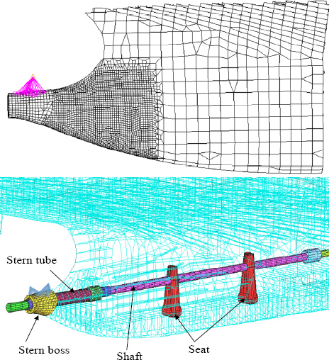
The target model is a 15K container ship powered by LNG fuel and FE-model is shown in Fig. 2(a). The structural analysis range under tandem block launching is shown in Fig. 2(b). There is no block from the bow to the deck house. The principal dimension of container ship is indicated in Table 1. In order to increase fuel efficiency, the knife shape was applied at the bow design without a bulbous bow.

Table┬Ā1
Principal dimensions of container ship
| Component | Value |
|---|---|
| Length O.A (Approx.) | 366.0 m |
| Length B.P (Moulded) | 360.0 m |
| Breadth (Moulded) | 51.0 m |
| Depth (Moulded) | 30.0 m |
| Design draught (Moulded) | 14.5 m |
| Scantling draught | 16.1 m |
During PE work, the block is supported by a tower support, and it is developed as a beam element as shown in Fig. 3. When the block is moved to the dock, the keel block is located on the bottom of the hull, and it is modeled as a spring element, as shown in Fig. 3.
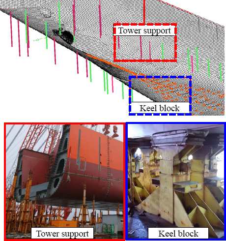
Fig. 4 shows the detailed modeling of the shafting system connected from main engine. It was modeled as 1-D beam element except for stern boss and tube.
2.3 Boundary and load condition
In the load condition of PE stage, a fixed condition was given to the tower support supporting the weight of the block. In order to express the behavior of the hull by seawater pressure during launch, the overall fixation at the lower part of the A.P., the widthwise restraints at the upper part, and the X and Y restraints were added at the end of the top edge near fore-end block as defined Fig. 5.

The launching condition of the tandem block were accurately reflected in the analysis model, and the weight consistency was 100% as shown Fig. 6. The center of gravity in the longitudinal direction of the hull was 99.5%, ensuring sufficient reliability.

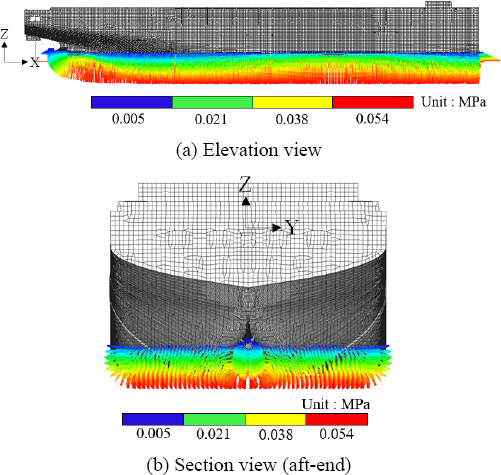
Fig. 7 shows the results of applying seawater pressure under launch. In this condition, significant deformation of the hull structure may occur to release the constraint force at the supporting points. Table 2 indicated the load conditions according to the five production sequences considered in the study.
Table┬Ā2
Load condition definition
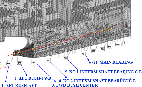
Fig. 8 and Table 3 shows information of the displacement calculation along with shafting system connected from the main engine to the stern bush. The location with the main support point was selected and the change of vertical displacement was analyzed. It consists of a 11 points, and 6 points are located only in the main engine.
Table┬Ā3
Information of displacement check positions
The selected measurement locations are also used in the shaft alignment calculation submitted to the classification society for audit.
The engine and shaft were developed by modeling with equivalent stiffness. This modeling technique is the same as the method suggested by the classification society10).
3. Results and discussion
From the using detailed FE-model based on the analysis procedure (see Fig. 1), static analysis11) performed calculation the relative displacement in the shaft system varying load conditions. The calculation position is same as defined in the Fig. 8.
Fig. 9 and Table 4 shows the relative displacement to the shaft system under LC-01 condition where the block is supported on the support in the PE yard. The maximum value occurs at the No.1 bearing point (ID 5), because this location is due to the large difference in structural stiffness of between main engine and bearing seat. The difference ratio of relative displacement of between No.1 and No.2 bearing positions is approximately 35%, on the other hand, there is a 79% difference between No.1 and first position in main engine. It can be confirmed that the deformation pattern depends on the shaft arrangement as well as difference in stiffness.
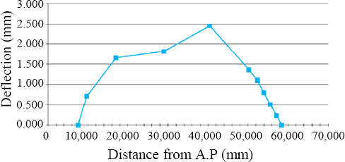
Table┬Ā4
Results of relative displacement according to shaft position under LC-01
| Point ID | Relative displacement (mm) |
|---|---|
| 1 | 0.000 |
| 2 | 0.718 |
| 3 | 1.650 |
| 4 | 1.810 |
| 5 | 2.445 |
| 6 | 1.362 |
| 7 | 1.100 |
| 8 | 0.806 |
| 9 | 0.513 |
| 10 | 0.231 |
| 11 | 0.000 |
Fig. 10 compares the results (LC-02) and the initial condition (LC-01) in which the deformation caused by welding is reflected actual block erection sequences above shaft line. In most locations, the displacement increased due to thermal deformation, and the location of the maximum change was at bearing No. 2 as shown Fig. 10 as well as Table 5. This effect is due to the amount of seam line by welding varying block volume.
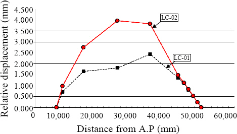
Table┬Ā5
A comparative displacement of between LC-01 and 02
Fig. 11 compares the deformed shape of No.2 bearing seat according to load conditions (LC-01 and LC-02). The displacement of the support point is similar, but the relative change is large because of the upward deflection caused by the welding heat.
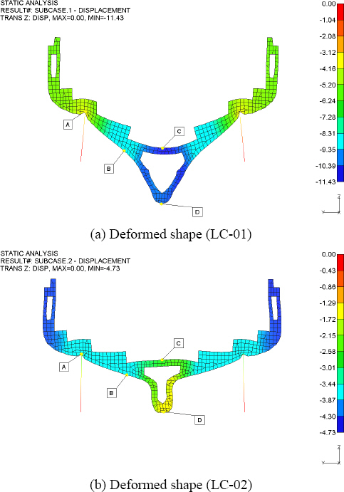
Fig. 12 shows the displacement distribution of the shaft system varying construction sequences. In the PE stage, the magnitude of difference value due to welding work (LC-02). Welding work is performed to construct a mega block, and as thermal displacement is added, shaft displacement increases within LC-02 and 03.

This result maintains the same pattern when moving to the dock through the lifting process. The magnitude of displacement appears to be the smallest to the shaft length due to additional buoyant forces under tandem floating condition(LC-05).
4. Conclusions
Numerical analysis was performed according to five major production processes to calculate the shaft centering of container ship. The FE-analysis is divided into structural strength analysis and thermal analysis, and the same model was used to increase the reliability of the results.
In this study, a procedure for determining the input required for shaft centering was proposed through a deflection review in five construction processes. The amount of relative displacement changes the most due to the effect of welding heat according to the block erection conditions, and the state of being installed in the dock is also large. As structural deformation occurs due to seawater pressure during launch, the final displacement pattern of the shaft system is restored similar to the initial PE condition. For shaft system alignment, it is necessary to understand the characteristics of these process changes, and it can be confirmed that there is a possibility of giving a large error if only fragmentary conditions are reviewed. As a future study, it investigates the severe load condition about shaft deformation according to construction process. To implement this, more numerical analysis and measurement data are needed.
 PDF Links
 PubReader
 ePub Link
 Full text via DOI
 Download Citation
 Print
Print