Recent Advances in Friction-stir Welding Process and Microstructural Investigation of Friction Stir Welded Pure Titanium
Article information
Abstract
The use of titanium and its alloys is increasing day by day, especially in aerospace, automobile, and defense fields. Friction stir welding is a prominent solid-state joining process, which produces non-melting low heat input welds with less residual stresses compared to the conventional welding process. The physical and chemical properties of Ti such as low thermal expansion and thermal conductivity, relatively high melting temperature(1668°C) and high reactivity makes the FSW a favorable joining process for Ti alloys. However, Ti friction stir welds reveal highly complexed microstructure evolution in the weld zone and exhibit several defects which can influence the mechanical properties of the weld. This paper aims at a review on the microstructural evolution and typical defects formation during the FSW of CP-Ti, with the brief review on the fundamentals of friction stir welding process and Ti and its alloys.
1. Introduction
In 1946, William Justin Kroll discovered the method to extract the Ti commercially and as a result of this the use of Ti and its alloys have been begun in earnest. Titanium and its alloys are extensively used in aerospace, military and navel applications because of their excellent property combinations such as high strength to weight ratio, corrosion and heat resistance and thermal stability.
Pure Ti is a silver-colored metal that has a close-packed hexagonal (HCP) crystal structure, known as alpha (α) phase, up to 883 °C. When it heated above a temperature of 883 °C, the phase transformation is occurred and change to the body-centered cubic (BCC) structure, which is called beta (β) phase. The transition temperature, also known as β transus, is affected by the amount of impurities or alloying elements in the Ti. β transus of commercially pure (CP) Ti is approximately 900 °C and Ti-6Al-4V, most commonly used α + β Ti alloy, is approximately 1000 °C.
The alloying elements in Ti are classified into α stabilizer or β stabilizer based on whether they increase or decrease the β transus1). The detailed classification of these alloying elements is provided in Table 1.

The structural application of Ti and its alloys certainly requires welding and joining. Ti can be welded with conventional fusion welding such as gas metal arc welding (GMAW), gas tungsten arc welding (GTAW), plasma arc welding(PAW), laser beam welding (LBW), electron beam welding (EBW), etc2). However, the high affinity towards oxygen and the low thermal conductivity of Ti make the fusion welding a challenging task. For- tunately, solid state welding processes are evolved as prominent techniques to produce high quality Ti welds. Friction stir welding (FSW) is such a solid-state joining process which can yield many advantages; such as narrow coarse structured HAZ due to the relatively low heat input during the process, and chance of less defects of fusion welding (cracks, inclusions, distortion and residual stresses).
This paper aims at a brief review on the fundamentals of FSW process includes the microstructural evolution and the types of defects formed during the FSW of CP-Ti.
2. Friction stir welding
2.1 Fundamentals
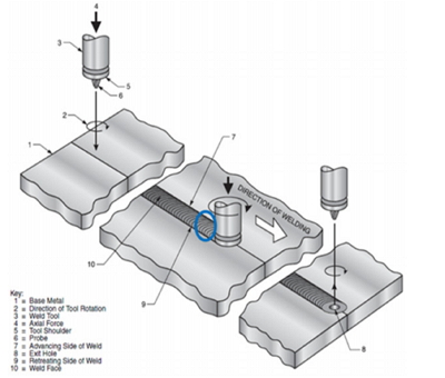
FSW is an autogenous solid state joining process invented by W. Thomas at The Welding Institute (TWI) in 1991 and was initially used for the welding of low melting materials such as Al, Cu, Mg, etc. FSW is a variant of friction welding that produces a weld between two or more workpieces by the heating and plastic material displacement caused by a non-consumable tool that traverses rapidly3). The typical nomenclature for the asymmetry of the FSW process relative to the weld centerline is indicated in Fig. 14). The side of weld where the tool traverse vector is parallel to the vector of tool rotation is called advancing side (AS), and the opposite side of weld where the tool traverse vector is counter parallel to the vector of tool rotation is called retreating side (RS).
The heating is achieved by friction between the rotating tool and the material, and this localized heating softens the material around the tool pin. Further, the combination of tool rotation and translation lead to the plastic flow of the softened material, along the rotation of the tool pin. Also, the axial force on the tool shoulder (4, 5 in Fig. 1) provides a forging effect on the top surface of weld and work as a constraint force against the displace of softened material to make weld. The trailing edge (blue circle behind the tool) swept around the tool to produce recoalescence. The severe plastic deformation at elevated temperature during the FSW process resulting in the generation of fine grained microstructure and there by good mechanical properties.
2.2 Equipment
FSW machine designs typically are supported by one of three different machine platforms, C-frame, gantries, or vertical structures similar to those used in boring mills4). FSW uses a specially designed non-consumable rotating tool which is inserted in to the material by giving the axial force and then traversed along the joint line7). Tools for the FSW are of three types namely fixed tool, adjustable tool and self reacting tool. Fixed tool is made of single piece for the constant thickness welding. Adjustable and self reacting tools are made of two (shoulder and pin) and three (shoulder, pin and bottom) independent pieces, respectively. Self reacting tool is also known as bobbin type tool. In Fig. 2, images of the typical FSW tools are illustrated42).
As well as the parameters of welding, the specification of weld tool also greatly affect the microstructure and the defect, hence the mechanical properties can be changed. During the FSW process, there are two types of different material flows by shoulder and pin. The shoulder drives the material by bulk and forges, while the pin drives the material layer by layer43). As illustrated in Fig. 2, various types of tool pin is there and it is evident that the specification of tool pin has a great influence on the material flows and its appearance. Nabeel Gharaibeh et al. have reported44) that the influence of three different tool-pin shape on the FSW of Al alloy. And Jimy Unfried-Silgado et al. have studied45) the effect of three different shoulder geometry of tool on microstructure and mechanical properties of friction stir welded Al alloy.
2.3 Parameters for welding
Like other welding processes, FSW also has several parameters for mechanized welding. The rotation speed influences the frictional heat, oxide layer breaking and mixing of materials. Tilt angle decides the appearance of the weld. And the welding speed (also called as travel speed) affects the appearance and the heat input of the weld. The down force of weld tool determines frictional heat and maintains contact condition between weld tool and material17).
An inappropriate rate of heating, can give rise to form FSW defects such as excessive flash, surface galling, nugget collapse, voids, surface grooves, tunnels, lack of penetration and lack of fusion24-32). Details of FSW defects are described in section 5 in this paper.
3. FSW of titanium and its alloys
3.1 Ti and its alloys
Generally, Ti and its alloys are classified based on their typical annealed microstructure: CP-Ti, α and near- a Ti alloys, α-β Ti alloys, and metastable or β Ti alloys1). CP Ti has various grades such as grade 1 to 4, based on minimum mechanical properties and maximum interstitial impurities. In general, strength variations are produced by the impurity contents, primarily the interstitial elements and iron.
On the other hand, α-β alloys are the mixture of α and β phases in their microstructure and the Ti-6Al-4V alloy is the most widely used, since its good formability and joinability. In such a two-phase Ti alloy, the act of alloying addition becomes more complicated and it leads to highly complexed microstructural appearance in final.
3.2 Typical microstructure of CP-Ti
Typical microstructures of CP-Ti are shown in Fig. 38). Initial microstructure of CP-Ti is profuse array of equiaxed grains, with a grain diameter of approximately 10 (grade 1) to 25 (grade 2) μm9-11). Fig. 3 a) and b) show the typical initial microstructure of CP-Ti along the longitudinal and transverse direction, respectively8). Further- more, Fig. 3 c) and Fig. 3 d) show the microstructure of CP-Ti after cold rolling along the longitudinal and transverse direction, respectively. Here, coarsened grains and high density of tangled twins are observed.

After the cold rolling, which means severe plastic deformation, high density of twins is observed as shown in Fig. 3 d). It is because of the limited number of independent slip systems of HCP13,14), and the low stacking fault energy (SFE) of α-Ti9,12).
3.3 FSW of CP-Ti
Owing to the high strength at high temperature, reactivity and low thermal conductivity of Ti make the friction stir welding a challenging task. Especially, the tool experiences a high level of wear and degradation during the welding. So, Ti and its alloys require tools made up of materials with wear resistance capabilities and strong mechanical properties at high temperature. Also, they require slower traverse rates and traverse speed than other materials such as Al, Cu and Mg.
Because of its high affinity with oxygen, nitrogen and hydrogen at temperature above 400 °C, welding must be carried out in inert or vacuum atmosphere. Also, the shielding or vacuum should be maintained until the material is cooled down below 400 °C.
4. Microstructure evolution of friction stir welded CP-Ti
4.1 Typical areas in FSW of CP-Ti
Typical low magnification optical microscope image of the conventional friction stir lap weldment is illustrated on Fig. 4. In the center of the weldment, stir zone (SZ) is exist; with the SZ as a center, transition zone (TZ) is observed on both sides of RS and AS. The section 4-2 and 4-3 deals with microstructure evolution of SZ and thermo-mechanically affected zone (TMAZ), respectively.
Low magnification overview of the friction stir lap welded CP-Ti
4.2 Microstructure evolution in the stir zone
Lee et al.10) reported that the grain structure in the SZ of α-Ti weldments are predominantly consist of twins. Moreover, the twin density appeared to be increasing towards the upper part of the weld owing to the compressive action of the shoulder of the tool.
Y. Zhang et al.17), have reported a detailed study on the stir zone microstructure of CP-Ti FSW made with a PCBN tool having a concave shoulder of diameter of 15 mm and a pin which was 45° tapered from 5.1 mm at the shoulder to a pin length of 2.0 mm. CP-Ti (grade. 2) sheet of 3mm thickness was partially penetrated with the travel speed and the rotational speed of 50mm/min and 200rpm, respectively. Fig. 5 a) reveals the low mag- ni fication overview with OM image, and Fig. 5 b) shows SEM images of five areas on SZ with cruciform as marked black squares in Fig. 5 a). In Fig. 5 b), the microstructure consisted of finer α grains than the base material, which are surrounded by more serrated grain boundaries, except in the surface layer which has lath- shaped grains. Previous studies18,19) have reported that the rapid cooling from a temperature above the β transus gives rise to an α single-phase microstructure having more serrated grain boundaries. From these results, it is reasonable to assume that the peak temperature was exceeded the β transus of the material during the FSW process. The average grain size of the α grains, i.e. five areas indicated in Fig. 5 b), was approximately 13μm and it is smaller than that of BM, about 27μm.

The cooling rate at any location after the FSW process with materials having low-thermal conductivity is relatively low. Coarsened and equiaxed HAZ, about 30μm in average, indicates that the cooling rate was relatively low. However, the allotropic transformation of β to α and a strain-rate induced by severe plastic deformation that shear and carry the material around the tool pin and shoulder helps dynamic restoration in SZ. Moreover, a high SFE of bcc β phase would prevent the dissociation of the dislocations. As a result the dislocation density is increased which support the dynamic restoration in SZ. From these results and discussions, it is reasonable to assume that dynamic restoration was occurred in the SZ of CP-Ti during the FSW process. So the average grain size in the SZ has greatly reduced even though the peak temperature exceeded the β transus of material and the cooling rate was relatively low.
4.3 Microstructure evolution in the transition zone
S. Mironov et al.9) have studied the complex grain structure development during FSW of CP-Ti. The material for this study was a 3 mm thick CP-Ti (grade. 2). The welding tool was made with Mo-based alloy and consisted of a convex shoulder having a diameter of 15 mm and a pin, tapered from 5.1 mm at the shoulder to 3 mm at the pin tip. The plunge depth was 2 mm, so partially penetrated butt joint was produced. The tool travel speed and the rotational speed was 60mm/min and 200 rpm, respectively. A low magnification OM image of friction stir welded CP-Ti is shown in Fig. 6. The portion highlited with a black rectangle represent the transition zone, which is an evidence for the grain structure development from base metal to stir zone through the TMAZ.

In order to gain the fundamental knowledge of FSW of Ti, one should understand the physical phenomena including fundamental issues of grain structure evolution. Fig. 7 a) shows the EBSD map of the transition zone with a length of around 3 mm (from Fig. 6) at the near- RS. It has been divided into three different regions: region 1 (Fig. 7 c) which is outer edge of the TMAZ and near the BM, region 2 (Fig. 7 d) where the grains become thinner with high aspect ratio, and region 3 (Fig. 7 e) where the grains drastically change. For the analysis of each area, high magnification EBSD images and misorientation distribution data are arranged in Fig. 7 c) to e). Moreover, for the comparison, EBSD mapping of BM and SZ also shown in Fig. 7 b) and f), respectively. Also, a 15° criterion was used to define low-angle boundaries (LABs) versus high-angle boundaries (HABs).

Composite EBSD map of the thermo-mechanically affected zone on the retreating side of the weld (a), with selected areas shown at higher magnifications in b-f). LABs and HABs are depicted as gray and black lines, respectively. Misorientation distributions and misorientation-axis distributions are also shown in b-f), respectively9)
In Fig. 7 b), HAB fraction of base metal is 70% and only sporadic LABs are clustered within some grains. Also, it contains wedge- and lens-shaped twins (arrowed). Local misorientations across the twin-matrix interface are typically close to 85° <21-1-0>, hence these are {101-2} twins. Misorientation of the base metal is characterized by a sharp low-angle peak and some clustering of misorientation.
Fig. 7 c) reveals region 1, and the original grains tend to be reoriented in the direction of the tool rotation. But the crystallographic orientation of parent grain does not change, thus the original two-component rolling texture still be recognized. In region 1, HAB fraction highly decreased (~29%) and LABs start to develop in the grain interiors, shown in the bottom right corner of the figure. The LABs tend to cluster near original grain boundaries, but frequently they extend across the grains and, in some cases, the extended LABs are coupled in pairs. The boundary traces of the extended LABs are close to the {101-0} prism slip plane trace, shown in the upper right corner of the figure. On the other hand, the rotation axes of the LABs are typically close to the <0001> pole. In this region, most interesting microstructural feature is transformation of the twin boundaries. This phenomenon can be explained by the deformation-induced crystallographic rotations of the twins and matrix from their initial orientation21).
Fig. 7 d) indicates the grains that have higher aspect ratio than the original grains. It results from the heat and local strain induced by the friction stir during the welding. Also, the grain boundaries of high aspect ratio become wavy and local migration start to occur. Prangnell P.B. et al.22) have reported on this phenomenon. It would be associated with a different mobility of the LABs and HABs. The LABs have a low mobility and the HABs have a high mobility. As arrowed bottom right side in Fig. 7 d), development of local grain boundaries migration leads to bulges along the original grain boundaries and eventually transform into fine grains. Moreover, as inset given in the top right side of Fig. 7 d), fine grains which are newly developed have been surrounded by HABs. It has equiaxed morphology and contains almost no substructure as encircled in Fig. 7 d). It creates a “neckless” structure that decorating the elongated original grains. Also, it significantly tends to coarsen in size and increase the volume fraction, as it has been closer to SZ.
A drastic change has been occurred in region 3, as illustrated in Fig. 7 e), an irregular mixture of HABs and LABs are the dominant microstructural feature and is evidently directional, preferentially, it tends to align practically parallel to the verge between the TMAZ and SZ. On the other hand, fine grains which are arrowed in Fig. 7 e) also have significance to microstructural component. Those fine grains are surrounded by HABs and contain virtually no substructures, opposite with the HAB/LAB “matrix”. As revealed chart of Fig. 7 e) and f), the misorientation is characterized by a broad irregular maximum in the angular range of ~5-50° and is somewhat unusual.
5. Typical defects of friction stir welded titanium
5.1 Types of defects
The friction stir weldability of a material can be assessed by the weld quality in terms of defects. Previous studies have proposed a process window based on welding parameters, and weld quality is a prominent weldability evaluation method23). Therefore, it is very important to study the different types of defects, and mechanism and reason for defect formation. Many researchers have done extensive studies on the defects in friction stir welding and they have classified as ‘volumetric defects’ and ‘weld line defects’25,28). However, this classification makes confusion as different defects arisen from different reasons are classified under the same category. For example, the joint line remnant which is caused by improper welding parameters and the kissing bond which is caused either by oxide layer entrapment or improper welding parameters are classified under the category of weld line defects. So, for better understanding, the defects are classified into two categories according to the cause of formation23).
1) Caused by inappropriate welding parameters
2) Caused by oxide layer or impurities on the surface and inappropriate welding parameters
The results that did not attached the reference number was conducted with the tool having a shoulder diameter of 15 mm, a pin diameter and length of 5 mm and 1.8 mm, respectively.
5.2 Defects by inappropriate welding parameters
Inappropriate welding parameters can lead to improper energy input and hence defect formation. Some of researchers25,28) have divided these kinds of defects into volumetric flaws and weld line flaws. On the other hand, it is more common to divide the defects based on the energy input, as illustrated in Fig. 823,25). The region outside of process window can be divided into three areas which are the principle reason for the defect formation in this category25,26).

The flash is a defect which is most commonly formed along the edge of SZ on the surface of weld. A large mass of flash or ribbon flash which are induced by the excessive heat input, forge load or plunge depth results in loss of the material (Fig. 9). Also, the excessive plunge depth or force load can form a depression on SZ (Fig. 10). Insufficient force load or plunge depth, in contrast, can induce groove-like defect on the surface of SZ (Fig. 11) which is continuous or intermittent top surface void in SZ34).
A large mass of flash and ribbon flash on the edge of retreating side of friction stir welded CP-Ti

A depression defect on the friction stir welded Ti-6Al-4V alloy
In the SZ, the longitudinal defect called tunneling defect is usually revealed, also called worm hole or channeling defect. As shown in Fig. 12, it is the tunnel of in-adequately consolidated and forged material that running in the longitudinal direction; which caused by the excessive heat input resulted from the high rotation speed and low welding speed.
A tunneling defect, cavity and void in the stir zone of friction stir welded CP-Ti
5.3 Defects by oxide layer or impurities on the surface and inappropriate welding parameters
Ti and its alloy have passive oxide film which is naturally oxidized upon exposure to the atmosphere. It is typically 3-10 nm thick and mainly composed of the stable oxide TiO235-38). The TiO2 is amorphous, and for the sound joint it should be broken up completely. Since the peak temperature of the FSW is not enough to melt and remove the TiO2 layer on the free surface of material, the tool rotation, traverse and plunge force will break up the passive oxide layer in case of the FSW process. If the parameters are not adequate for completely break up the oxide layer, so the oxide film is present on the faying surfaces during the welding, some of critical defects will be formed; then it will deteriorate the mechanical properties of weldment.
Cavity and void can be formed which are due to abnormal stirring, inadequate shielding or surface oxide layer and impurities (showed in the bottom of Fig. 12).
Lazy-S and kissing bond are well known defects which are induced by remnant of oxide layer or particle during the welding. Fig. 13 shows the images of typical oxide induced defects. Some of previous research has unveiled the formation mechanism of these defects. Oosterkamp et al.39) found that formation of these defects was related to the insufficient breaking up of oxide layer. Reynolds et al.40) suggested that the zigzag line in the stir zone is the remnant of the oxide layer on the surface before welding. Sato et al.31) suggested that the microstructure around the root tip of the zigzag line is fragmented initial oxide layer on the butt surface. And it was locally distributed as oxide particles during the FSW. Moreover, Sato et al.41) suggested that degree of the collective movement of the oxide particles is depending on the welding parameters that of degree of stirring increases with the heat input. So, the weak degree of the stirring, i.e., lower heat input, would result in the local and dense distribution of the oxide particles. And it leads to form the zigzag line flaws in the SZ. It is also can observe in both edge of weld surface, and edge of contact area on lap joint welds (also called as hooking). Typical images are shown in Fig. 14 and 15, respectively
Oxide induced defects on the edge of retreating side of SZ (CP-Ti)
Oxide induced defects on the edge of contact area on the lap joint friction stir welding (CP-Ti)
6. Closing remarks
FSW process can be successfully applied for several materials which are challenging to join with conventional joining processes. Because of several advantages such as generation of fine grain in the weld zone, and relatively less heat and residual stress, this process is favorable to the joining of Ti and its alloys. Even though, the occurrence of defects, owing to the improper parameters of FSW and/or the oxide and impurities on the base material, is still a major concern, the process is getting the spotlight and opening totally new domain of joining. It is evident that the welding parameters and tool type is most dominant factors to determines microstructure evolution and the defects formation mechanism. But, there are many uncertain phenomena still exist and which need to be explained by further research. This review paper addressed the mechanism of microstructural evolution and the typical defects formation during the FSW process, with brief introduction of FSW process, and the Ti alloys.
Acknowledgement
This work was supported by Dong-Eui University Grant (201702750001) and a Grant (16-CM-MA-10) from Civil-Military Technology Cooperation Program funded by the Ministry of Trade, Industry and Energy (MOTIE), Republic of Korea.