Weldability Study on SS 304B4 Joined using Boron Containing Austenitic Stainless Steel Consumable
Article information

Abstract
304B4 stainless steel contains ~1.2 wt.% of boron intentionally added for neutron shielding purposes in nuclear power plants and nuclear waste storage applications. Weldabilty of 304B4 stainless steel is generally con- sidered to be poor because boron is almost insoluble in austenite phase and has a tendency to segregate in the liquid phase during solidification. This results in formation of different types of borides in the eutectic which melts at low temperature and makes the steel susceptible to cracking. Among the welding consumables specified in standards and codes, E309 consumable is the one generally recommended for this steel, but electrodes with controlled addition of boron (E308BRN) is also available. A systematic study on solidification cracking susceptibility of 304B4 stainless steel weld joint prepared using E308BRN containing ~1 wt.% B has been carried out. Further, mechanical properties of weld joints made with this electrode are compared with that made from E309 electrode. Results show that E308BRN electrode can be chosen for applications involving low restraint forces to produce crack free joints. Mechanical properties of the joints made with both E308BRN and E309 are poor when compared to the base metal. This is attributed to continuous network of eutectic borides present in the interdendritic regions of fusion zone and partially melted zones of the weld joints.
1. Introduction
Borated stainless steels (SS) are austenitic SS containing boron (B) in the form of chromium borides (Cr2B) distributed in the austenite matrix. These steels are generally used where neutron shielding is intended to protect structural components from neutron irradiation in a nuclear reactor. They are covered by ASTM standards A 887 which includes eight boron levels lowest starting from 304B1 to the highest in 304B8. In each type, the steel is again categorized into two grades A and B based on mechanical property requirements of the final component1). Among these 304B4 Grade B SS has been chosen for fabrication of neutron shield to protect intermediate heat exchangers in Indian prototype fast breeder reactor (PFBR)2). Other applications of this steel include construction of fuel storage racks, casks for storage of densified spent fuel etc. to prevent streaming of neutrons which may cause unforeseen criticality during storage or transportation3,4).
Weldability of 304B4 SS base metal has reportedly been stated that the steel is weldable under moderate restraint forces5,6). Standard E309 electrode is the recommended electrode for welding 304B4 SS as per codes7). Though boron containing consumables are also commercially available, joining of this steel using the recommended 309 electrode caused severe hot cracking during fabrication of 304B4 SS neutron shields of thickness 10-28 mm2). Our earlier work on hot cracking susceptibility of 304B4 SS base metal revealed that solidification cracking susceptibility of the 304B4 base metal containing 1.3 wt.% B is insignificant because of eutectic backfilling taking place in the hot cracks8). Hence, neutron shields for PFBR were fabricated using a special electrode E308BRN consisting of about 1 wt.% B. It is to be noted that E308BRN is not a standard electrode for welding 304B4 SS. As the B content of the weld metal is similar to that of the base metal, it was considered for joining 304B4 SS plates for fabrication of neutron shields in PFBR. A systematic study was then carried out on weldability of 309 weld metal deposited using E309 electrode since it exhibited severe cracking tendency during welding. From the study it was deduced that 304B4 SS joined using E309 electrodes was highly susceptible for weld metal liquation cracking due to dilution of base metal in the weld metal. Though E309 electrode is free of B, base metal dilution caused a gradient in the weld metal boron content from the center of the weld towards the interface which significantly increased the liquation cracking susceptibility of the weld metal. A region in the weld metal where B content dipped below 0.4 wt.%, the cracking susceptibility was found to be very high due to insufficient eutectic liquid to back fill the cracks9). Even the existing literature on weldability of borated stainless steel states that solidification cracking is unavoidable if the boron content of the steel is below 0.5 wt.%10).
In the present study, weldability of boron containing weld metal was intended to evaluate its hot cracking tendency. So, a systematic study was carried out to evaluate the hot cracking susceptibility of boron containing 308 weld metal deposited using E308BRN electrode by multipass SMAW process to join 304B4 SS plates. Since the electrode was used for welding borated stainless steel, mechanical properties of the weld joint are also worth studying and hence presented in this study. The mechanical properties of 304B4 weld joint prepared using E308BRN electrode is compared with that prepared using recommended E309 electrode and the base metal.
2. Experiment Details
2.1 Materials
304B4 SS plates of size 300x300x12 mm were used for preparation of weld pads using E308BRN and E309 electrodes and welding parameters as shown in Table 1. Chemical compositions of base metal, undiluted E309 and E308BRN electrodes deposited as per AWS specification 5.4 is shown in Table 2. According to AWS 5.4 specifications for preparation of weld pad for chemical analysis of undiluted weld deposit, weld pads of length 50 mm, width 13 mm and height 16 mm was deposited in flat position on 304 stainless steel base metal using E308BRN and E309 electrodes of 4 mm diameter. The samples were extracted from the deposited weld metals at height of 13 mm from the surface of the base metal as recommended by the code.

Welding parameters used for joining 12mm thick 304B4 SS using E308BRN and E309 electrodes
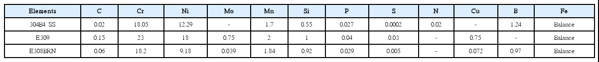
Chemical composition of 304B4 SS base metal and electrodes used for fabrication of weld joints in wt.%
2.2 Test Procedures
Hot crack specimens of dimensions 127×25×3 mm were extracted from the weld pad such that the weld metal remains at the center as shown in Fig. 1. To evaluate the hot cracking susceptibility of the weld joint, transverse and longitudinal varestraint tests were carried out on these specimens using parameters shown in Table 3 and the procedure described elsewhere11). Lengths and widths of the cracks present on tested specimens were measured using stereo microscope at 60x magni- fication. Full size Charpy- “V” notch cross weld impact test specimens of dimension 55x10x10 mm were extracted from both the weld joints and room temperature impact tests were carried out according to ASTM standard E-23. The notch was positioned exactly at the centre of the weld oriented along the welding direction. Cy- lindrical cross weld tensile specimens of gage length 25 mm and L/D ratio of 6.25 were extracted from the weld pads and tested at room temperature according to ASTM standard E8-04. Also, full size charpy “V” notch impact and tensile tests were carried out at room temperature on 304B4 base metal according to ASTM standards for comparison. Metallography specimens extracted from both the weldments and hot crack tested specimens were polished up to 1 micron diamond finish and etched electrochemically using oxalic acid for microstructural characterization using light and scanning electron microscopy. Elemental mapping was carried out on base metal and weld metal regions of transvarestraint tested specimens using Wavelength Dispersion Spectra (WDS) equipped Electron Probe Micro Analysis (EPMA) especially for quantification of boron. Metallo- graphically prepared specimens were also used for microhardness survey across the weldment using Vicker’s microhardness tester of “Bowers” make at 500g load. Three profiles were taken on individual specimens and the average of three readings is plotted with standard deviation as error bar.

Schematic of extraction of hot crack specimens from the weld joint used for (a) Transvarestraint (TVT) (b) longitudinal varestraint test (LVT) showing the direction of autogenous TIG welding and loading during testing
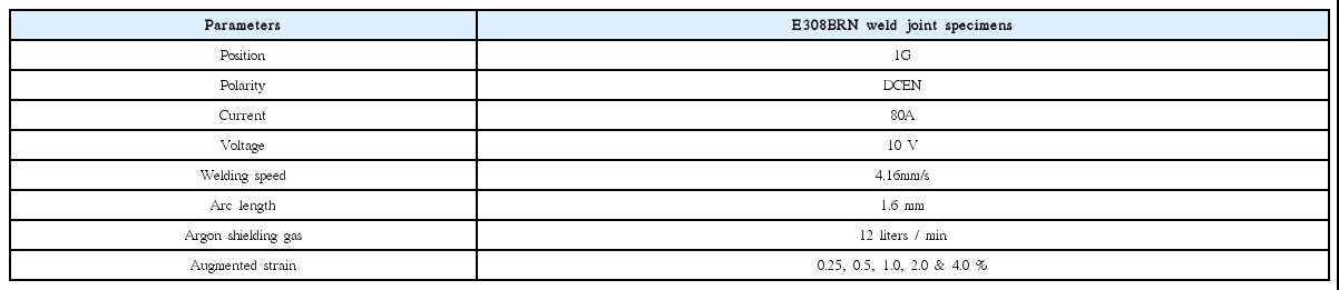
Parameters used during transverse and longitudinal varestraint tests carried out for E309 and E308- BRN weld joint specimens
As shown in Table 2, B content of the base metal was found slightly higher than that present in the electrode. In order to estimate the difference in their solidification temperature range which has direct correlation with hot cracking sensitivity, Scheil’s solidification simulation for 304B4 SS base metal and 308BRN weld metal composition was performed using ThermoCalc software version 6 using TCFE8 database.
3. Results
3.1 Microstructural Characterization
3.1.1 Base metal microstructure
The base metal microstructure was composed of austenite matrix with 5-10 micron sized chromium boride (Cr2B) precipitates embedded in it. Fig. 2 shows the microstructure of 304B4 base metal observed using light microscope.
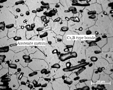
Microstructure of 304B4 stainless steel base metal consisting of Cr2B type borides distributed in the austenite matrix
3.1.2 Weld metal Microstructure
(a) 308BRN weld metal
308BRN weld metal microstructure was composed of primary austenite dendrites with interdendritic austenite/ boride eutectic constituents. Fig. 3 shows the microstructure of 308BRN weldment obtained using optical microscope. The area fraction of austenite + boride eutectic constituents was estimated to be ~0.32 using image J software by appropriately adjusting the contrast of the image and the value reported is an average of readings taken from 10 images obtained from different locations of the weld metal. Also, from the analysis, distribution of eutectic borides appears to be uniform across the weld.
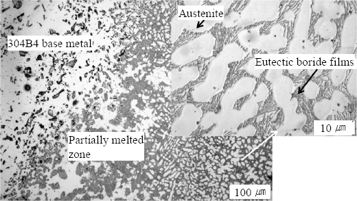
Microstructure of 308BRN weldment at low magnification with high magnification image of 308BRN weld metal microstructure in the inset
(b) Partially melted zone (PMZ)
308BRN weldment consisted of partially melted zone adjacent to the weld joint interface where partially molten and solidified base metal austenite grains are surrounded by islands of austenite- boride eutectic phase as shown in Fig. 3. The peak temperatures across this region lies in between the liquidus and solidus lines of the equilibrium phase diagram of this hypoeutectic alloy system as shown schematically in Fig. 4. The PMZ region adjacent to the unaffected base metal on reaching the eutectic temperature corresponding to the reaction γ + (Fe,Cr)2B↔L, undergoes liquation and solidifies as eutectic without any change in its composition (CE) exhibiting finger print morphology as shown in the microstructure in Fig. 4. From this point to locations closer to fusion line, the peak temperatures experienced by the PMZ is further above the eutectic temperature but below the liquidus temperature. With increasing peak temperatures on nearing the fusion line, the fraction of liquid also increases by melting more of the primary austenite phase (γ). By this way the composition of the eutectic liquid also deviates towards hypoeutectic compositions as indicated by C2 and C3 from that of the eutectic composition (CE). On cooling, the liquid in PMZ at a temperature above the eutectic point of the alloy system initially solidifies as γ and as γ + (Fe,Cr)2B eutectic in the interdendritic region towards the end of solidification as the final liquid reaches the eutectic composition.

Schematic illustration of formation of Partially Melted Zone (PMZ) in 304B4 SS stainless steel weldment
(c) Microstructures of hot crack tested specimens
Microstructure in Figs. 5(a) & (b) shows the presence of solidification cracks along the interdendritic regions of refused zone (formed during varestraint test) of 308BRN weld metal after transverse varestraint test at 4% augmented strain. The weld bead deposited during the transvarestraint test is termed as “refused zone” because the tests were carried out on the weld metal regions of the specimens extracted from weld pad prepared using E308BRN electrode. The weld metal which is already in fused and solidified condition undergoes fusion and solidification once again during the transvarestraint test and hence, it is termed as refused zone. In these microstructures, it is observed that except for a few fine cracks, there is no eutectic backfilling occurred in the major cracks. Fig. 5(c) shows solidification cracks observed on 308BRN weld metal specimen tested at 1% augmented strain which shows many fine back filled cracks and one centre line crack which is also almost 90% back filled. Overall, by observing these microstructures it can be stated that back filling by eutectic is effective only in small and fine cracks but not in long and wide ones.
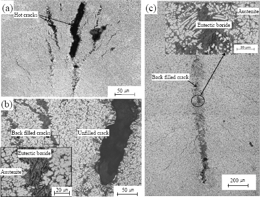
Microstructures obtained from 308BRN weld joint specimens after transvarestraint tested specimens at (a) 4% augmented strain (low magnification) (b) 4% augmented strain (high magnification) (c) 1% augmented strain
(d) Micro chemical analysis using Electron Probe Micro Analyzer (EPMA)
Results of micro chemical analysis carried out on E308BRN transvarestraint tested specimens using EPMA is shown in Fig. 6. The elemental mapping obtained in the austenite and eutectic phases present in the specimen showed clear indications that the borides formed in 308BRN weld metal is non equilibrium Fe rich borides as compared to Cr- rich borides found in 304B4 SS base metal.

Elemental mapping on austenite matrix and eutectic borides (a) 304B4 SS base metal and (b) 308BRN weld metal
3.2 Solidification simulation
Temperature (T) - Fraction of liquid (fL) curves generated for 304B4 SS base metal and 308BRN weld metal compositions using Scheil’s solidification simulation is shown in Fig. 7. It is observed that the freezing range of 308BRN weld metal is 35°C more than that of 304B4 base metal. The prediction gives an indication that 308- BRN could have slightly higher propensity for cracking than the base metal.

Temperature vs fraction of liquid (fL) curves generated for 304B4 SS base metal and 308BRN weld metal using Scheil’s solidification simulation module
3.3 Hot cracking susceptibility
The results of varestraint test plotted in Fig. 8(a) and (b) shows average Total Crack Length (TCL) and Maximum Crack Length (MCL) vs % augmented strain respectively calculated from the measured crack lengths found on transverse varestraint tested specimens extracted from the weld pad. Each point in Fig. 8(a) represents an average of TCL measured from 3 specimens tested at same augmented strain. It is clearly evident that TCL saturated at 2% augmented strain which means that TCL obtained beyond 2% augmented strain remained almost constant even at higher applied strain. From TCL data it is quite discernable that E308BRN weld is moderately susceptible to solidification cracking. MCL vs % augmented strain data shows that MCL increases with respect to increase in % augmented strain. It was found that MCL was almost saturated at 2% augmented strain. This shows that an augmented strain of 2% is sufficient to open up the entire length of liquated region in the solidifying weld metal. Specimens tested in longitudinal varestraint method revealed low sensitivity for cracking on the surface and hence not considered.

(a) Total Crack Length (TCL) and (b) Maximum Crack Length (MCL) obtained from crack length measurements carried out on transvarestraint tested specimens extracted from 304B4 SS joined using E308BRN plotted against % augmented strain
3.4 Mechanical Properties
3.4.1 Tensile properties
Flow curves obtained from tensile tests performed on the weld joints and the base metal are shown in Fig. 9. It is found that the base metal has good ductility. Both the weld joints showed poor tensile properties. The cross weld tensile specimens taken from 309 weld pad failed along the region in the weld metal highly diluted by the base metal whereas the specimens taken from 308BRN weld pad failed in the partially melted zone (PMZ) of the weldment as shown in the Fig. 10. It is found that tensile properties of weld joints are poorer than the base metal properties.

Stress-strain curves of 304B4 SS base metal, 304B4 SS weld joints prepared using E308BRN and E309 electrodes tested at room temperature

Microstructures at the fracture location taken after tensile test at room temperature (a) E308BRN weld joint (b) E309 weld joint
3.4.2 Impact properties
The impact toughness values of 309 weld metal and 308BRN weld metal at room temperature was 50 and 10 J respectively. The toughness values obtained for 304B4 base metal was 20 J. The fractographs of impact tested specimens of the weld joints are shown in Fig. 11.

Fractographs taken after room temperature impact test with the notch at the weld center carried out on cross weld specimens extracted from weld joints prepared using (a) E308BRN and (b) E309 electrodes
Fractographs taken on the fracture surfaces of the impact tested specimens shows complete cleavage facets in 308BRN weld specimens whereas dimple morphology for 309 weld metal in Fig. 11. The observed fracture morphologies of the weld joints confirmed that 309 weld metal center does not contain embrittling boride eutectic phase that is present in E308BRN weld.
3.4.3 Microhardness Survey across the weldments
The microhardness profile taken across the weldments made of 309 and 308BRN is shown in Fig. 12. The hardness values of 308BRN and 309 weld metals were 250 ±30VHN and 210±20VHN respectively. At the weld-base metal interface where there exists a partially melted zone (PMZ) sandwiched between weld and the base metal as shown in Fig. 3, the hardness value was found to be as low as 200 ± 10 VHN in case of both E309 and E308BRN weldment. The base metal hardness value was found to be ~220VHN.

Microhardness profiles taken across weld joints prepared using E308BRN and E309 electrodes
4. Discussion
4.1 Hot cracking susceptibility of E308BRN weld metal
E308BRN weld metal consists of austenite dendrites and a continuous network of interdendritic austenite boride eutectic constituents as shown in Fig. 3. In this case, B content of the weld metal is almost similar to that of base metal and therefore a uniform microstructure could be observed from the weld interface to the center of the weld metal. The area fraction of eutectic phase in the weld metal has been estimated around 0.32 uniformly distributed in the microstructure. On straining the specimen rapidly during the transvarestraint test, the liquated dendritic boundaries could not accommodate the augmented strain and hence resulted in severe cracking at higher augmented strains. The threshold strain for cracking was ~0.5% which is the minimum strain required for hot cracking to occur. Values of TCL and MCL saturated at 2% augmented strain which implies that the cracking susceptibility is independent of applied strain beyond 2% augmented strain, in other words, it can be said that the crack length has reached the maximum extent of liquated portion in the weld region. In general the observed range of threshold and saturated strain for fully austenitic stainless steel and Ni based alloys are 0.5-2% and 5-7% respectively12). In the present study, for E308BRN weld metal the saturated strain itself falls in the regime of expected threshold strain for austenitic alloys. This shows the relative cracking susceptibility of the investigated alloy is comparatively higher than other fully austenitic alloys.
Also, it was observed that majority of the cracks were long and wide in the specimens tested at 2 and 4% augmented strain levels and only a few fine cracks were completely backfilled by the eutectic constituents as shown in Fig. 5(a). It is noticeable from the microstructure that the cracks that were long and wide remained open and were hardly backfilled by the eutectics. It has been reported that backfilling of the cracks by eutectic liquid takes place by the phenomenon of capillary absorption13). Thus the back filling mechanism follows capillary action theory which states that capillary rise is a function of liquid density/viscosity, column radius/ length and surface energy14). The height (h) of the liquid drawn into the column is given by equation 1 which is derived from Jurin’s law15).
Where,
h = Capillary rise of liquid in the column
DL = Density of Liquid
γ LV = Surface tension
R = Radius of the column
g = Acceleration due to gravity
q = Contact angle between liquid and column
Basic assumptions made before applying equation (1) to our case is that temperature is uniform across the solid- liquid interface so that there is no fluctuation of density of liquid and surface tension is constant. The assumptions are reported to be quite reasonable since only small fraction of liquid is drawn from the liquid metal ahead of the solid- liquid interface of the weld pool13). Except for the parameter radius of column (R), all the other parameters remain constant for the specimens tested at different augmented strain levels. The parameter R corresponds to the width of the crack in the context of backfilling of hot cracks during varestraint testing. Fig. 13 shows the widths of longest cracks plotted against corresponding augmented strain observed in transvarestraint tested specimens. It is evident from Fig. 13 that with increase in augmented strain, crack width increases correspondingly. By comparing the microstructures of hot crack specimens tested at 1% and 4% augmented strain (Fig. 5), it is clearly seen that at low augmented strain where the cracks are short and narrow, back filling by eutectic is more or less complete in case of fine cracks. Whereas, at high augmented strain, the cracks that are very long and wide are backfilled sparsely. This shows that effective backfilling by eutectic liquid occurs in short and narrow cracks than in the cracks that are wide and long. From the results it can be inferred that in case of near eutectic alloys, where the fraction of eutectic liquid formed is as high as 0.3, hot cracking is likely to occur when high restraints are imposed during welding. At low restraint levels, solidification cracks formed in the welds are healed by backfilling of eutectic liquid. This is in contradiction to transvarestraint tests conducted on 304B4 base metal containing 1.3 wt.% B similar to that of E308BRN which revealed very low hot cracking sensitivity because of extensive backfilling of the cracks by the eutectic constituents at all strain levels in our earlier work8). The reason for this has been attributed to presence of abundant amount of liquid, ~0.41-0.44 area fraction as analysed from the fusion zone microstructure shown in Fig. 14(a)8). This eutectic liquid was available for healing of the cracks formed in the welds. In the present study, 308BRN weld metal microstructure shown in the Fig. 14(b) contains ~0.31-0.32 area fraction of eutectic liquid which is found be deficit to back fill the cracks in the refused zone at higher augmented strain. Also, it can be observed from the results of Scheil’s solidification simulation of 304B4 base metal and 308BRN weld metal shown in Fig. 7 that the solidification range of 308BRN weld metal is 35°C more than the 304B4 SS base metal. Robino et.al has successfully modeled the solidus and liquidus temperatures of borated stainless steels as function of boron content which also shows an increase in the freezing range with respect to decrease in the boron content16). This also could be a factor contributing to increase in the hot cracking susceptibility of 308BRN weld metal as compared to 304B4 base metal. Further, in our earlier study, it has been shown that there is a considerable enlargement in freezing range for refused borated stainless steel due to formation of kinetically favored Fe rich eutectic borides during solidification. Since the melting temperature of Fe rich borides are lower than equilibrium Cr rich borides17), the propensity for hot cracking is further enhanced. In the present study, comparison of base metal and 308BRN weld metal boride microchemistry examined using EPMA/WDS also shows that the borides present in this weld metal is also rich in Fe as compared to base metal borides which is similar to that reported in our earlier study on solidification cracking susceptibility of 304B4 base metal. On the whole, there are multiple factors interplaying as discussed above which contribute to hot cracking phenomenon in E308BRN.

Width of the longest crack observed in the transvarestraint tested specimen at various % augmented strain

Microstructures of fusion zone of varestraint test specimens (a) 304B4 SS base metal (b) 308BRN weld metal
4.2 Comparison of mechanical properties of E308BRN and E309 weld joint
The flow curves of the two weld joints and base metal can be compared in the plot given in Fig. 9. As it is very common to find base metal tensile properties to be superior than weld joint properties18), 304B4 base metal also shows good ductility as compared to 309 or 308BRN weld joints. It is not uncommon to observe such behavior because the base metal is a wrought product composed of uniform microstructure. The base metal microstructure of 304B4 SS shown in Fig. 2 is a consequence of hot rolling operation performed on the cast ingots. During rolling operations the eutectic structure is broken down and distributed as isolated borides in continuous austenite matrix.
In 308BRN weld joint, though weld metal composition is similar to that of the base metal, there is a large variation in microhardness values of the base metal and the weld metal as shown in Fig. 12. The values obtained across the weld zone were at least 50-70VHN more than the base metal which can be attributed to as cast microstructure of the weld zone consisting of austenite and interdendritic eutectic borides as shown in Fig. 3. Impact toughness value (10 J) of E308BRN weld metal also shows that it is highly embrittled by the interdendritic eutectic phases. Also, it is evident from Fig. 12 that there is a hardness dip in the PMZ region which suggests that the region has lower strength than the other regions of the weldment. In this context it can be argued that higher yield strength exhibited by 308BRN weld joint than the base metal could be because of the constraint effect from the composite microstructure with large variations in strength present in the weld joint. It can be noticed that the tensile failure of the joint occurred along the partially melted zone as shown in Fig. 10(a). By correlating the microstructure adjacent to the fracture location and the stress- strain curve in Fig. 9, it is evident that the failure has taken place catastrophically without any elongation by linkage of voids at eutectic-matrix interface in the PMZ. Since PMZ is the location in the weldment where complete grain boundary liquation occurs as shown in the Fig. 3, propagation of cracks occurs easily along the liquated grain boundary.
Whereas, the microhardness profile taken across E309 weld joint shows more or less uniform strength across the weldment. This aspect is also reflected in the tensile behavior of the weld joint as the yield strength of the joint closely matches with that of the base metal, as shown in Fig. 9. The failure has occurred along the region in weld metal highly diluted by the base metal. Fig. 10(b) shows austenite dendrites and interdendritic eutectic borides in the microstructure adjacent to the failure location. The interdendritic eutectic borides are formed due to mixing of boron in the weld metal as a consequence of base metal dilution during welding. Though originally, E309 electrode does not contain boron, the weld metal chemistry is altered during welding of 304B4 steel using E309 electrode9). Microhardness data obtained in E309 weld metal region away from weld interface towards the center where base metal dilution is expected to be low is consistently around 200 VHN whereas, in the weld interface region where dilution ratio is very high the micro hardness values were found to be marginally high. Again there is an increase in the microhardness values (Fig. 12) immediately after the weld interface due to presence of 304B4 unmixed zone as shown in microstructure of weldment extracted from 309 weld pad in Fig. 10(b). The poor tensile properties of E309 weld joint is attributed to embrittling effect of eutectic borides present in the interdendritic regions as shown in the microstructure (Fig. 10(b)). Fig. 15 shows SEM image of tensile specimen extracted from 309 weld joint near the fracture location. It can be observed that the voids are present along eutectic -austenite interfaces which indicate that the failure has taken place due to weakening of interdendritic regions by the presence of eutectic borides. Impact toughness obtained from 304B4 weld joint with the notch at 309 weld center was 50 J which is consistent with the value ~54 J reported for all weld E309 weld metal impact toughness at room temperature19). It seems at weld metal center, the base metal dilution is very negligible as mentioned earlier and therefore the weld metal impact toughness remained unaltered. The microstructure of 309 weld metal adjacent to the facture location reveals only austenite dendrites and interdendritic delta ferrite as shown in Fig. 16. At the same time it is to be noted that the impact toughness value at the weld joint interface may be less than that observed at weld center due to eutectic boride network observed at this region as shown in Fig. 10(b).
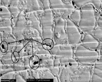
SEM image of tensile tested specimens extracted from 309 weld joint showing voids in the interdendritic regions near the fracture location

Microstructure of 309 weld metal taken adjacent to fracture location on impact tested specimen
5. Conclusion
1) Boron containing E308BRN weld joint is found to be moderately susceptible for solidification cracking during multipass welding due to ineffective backfilling by Fe-rich eutectic borides in long and wide cracks. However, E308BRN electrodes can be used for applications involving low to moderate restraint forces during welding to produce crack free joints.
2) Tensile properties of both E309 and E308 weld joints are poor due to the presence of eutectic borides in the interdendritic regions of E309 weld metal diluted by base metal in and intentional addition of B in case of E308BRN.
3) E309 weld joint consist of more or less uniform strength across the weldment though microstructures across the weldment are not uniform.
4) E308BRN weld joint shows large mismatch in strength between the weld metal and base metal and hence failed in a brittle manner without any ductility. Although, the electrode has similar composition as that of the base metal.
5) Poor impact toughness observed in E308BRN weld metal is attributed to as cast structure of the weld metal consisting of continuous network of eutectic borides along the interdendritic regions. Whereas, good impact toughness shown by E309 weld metal is due to presence of only austenite - ferrite duplex microstructure and no traces of eutectic boride.
Acknowledgements
The authors acknowledge support received Mr.Arul for his support during hot cracking experiments and weld pad preparation. The authors are also thankful to Mr. V.Rajnikanth, MST Division, CSIR-National Metallurgical Laboratory, Jamshedpur.