Technical Issues in Fusion Welding of Reduced Activation Ferritic/Martensitic Steels for Nuclear Fusion Reactors
Article information

Abstract
Reduced activation ferritic/martensitic steels (RAFMs), which are the modified variants of 9Cr-1Mo heat resisting steels, have been recognized as candidate structural materials for the blanket module of nuclear fusion reactors. Since the blanket is exposed to a high flux of neutrons and complex periods of fluctuating mechanical and thermal stresses, evaluation of the high-temperature mechanical properties of both the RAFM steel and welds, and understanding of their degradation behaviors, are needed to provide feedback for the development of better RAFM steels and welding processes. In this review article, first, several welding processes used to fabricate the blanket modules are introduced. Microstructural evolution during fusion welding of the RAFM steel and its subsequent degradation during creep and/or irradiation are reviewed. The thermal stability of the RAFM steel originates from solid solution strengthening, sub-grain hardening and precipitation hardening. The degradation of the RAFM steel is discussed in terms of matrix recovery associated with lath widening and reduction of dislocation density, coarsening of precipitates and the formation of Laves and Z phases. This work helps provide insight on how to mitigate the microstructural degradation, and design optimal welding technology.
1. Introduction
Reduced activation ferritic/martensitic steels (RAFMs) have been considered as the candidate structural materials for blanket module of nuclear fusion reactors1-3). The RAFM steel was derived from variants of modified 9Cr-1Mo heat resisting steel. The RAFM steel involved the replacement of Mo in the modified 9Cr-1Mo steel by W (1-2 wt.%) and/or V (0.2 wt.%)3,4). Nb was substituted by Ta (0.02-0.18 wt.%). Since the blanket is exposed to high flux of neutron and complex periods of fluctuating mechanical and thermal stresses, the RAFM steels are expected to experience stress/irradiation-induced non-equilibrium phases formation as well as coarsening of precipitates because of its high contents of Cr, W, V, Ta, which can affect high-temperature properties. Accordingly, the chemical composition optimization has been extensively studied to assure the excellent properties of RAFM steels based on the research programs in European Union, USA, Japan, China, India and Korea2-9).
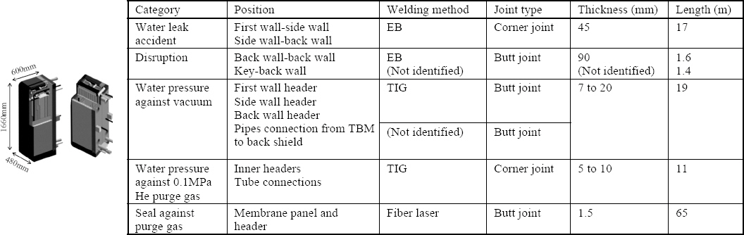
The blanket is an important device trapping the core plasma under extremely high heat load and neutron irradiation environment. This blanket provides multiple-functions to convert kinetic energy of neutrons generated in the fusion reaction into heat energy (heat exchange), to shield neutrons, and to multiply tritium from lithium in the coolant1-3). The blanket is composed of about 400 to 500 boxes to form an outer wall which is in primary contact with the plasma. The blankets should be fabricated as final parts by assembling materials that perform different functions. Therefore, welding and joining techniques of homogeneous or dissimilar materials are considered as core technologies for blanket manufacturing. The first wall in contact with the plasma is fabricated by joining protective materials such as beryllium (Be) or tungsten (W). Other parts of the blanket is fabricated by using fusion welding of RAFM steel. Fig. 1 shows the “Water-Cooled Solid- Breeding (WCSB)” blanket system considered as the Test Blanket Module (TBM) for ITER in Japan and the welding methods actually applied. In order to welding the RAFM steel, TIG (Tungsten Inert gas)10-17), EB (Electron Beam) welding14-18) and HIP (Hot Isostatic Pressing) bonding are most frequently performed19-23).
In this review paper, the microstructure evolution during welding of RAFM steels is addressed. Their high- temperature properties and irradiation resistances of RAFM welds are discussed in terms of their microstructure degradation. In particular, it is intended to provide an insight how to develop the welding technology for improving the welds performance. This review paper consists of most of the information presented in the previous column24).
2. Microstructure Characteristics of RAFM Steel Weld and Type IV Issue
RAFM steels are subjected to normalizing and tempering treatment to achieve the stable tempered martensitic microstructure. The microstructure shows the several elements such as prior austenite grain boundaries (PAGBs), blocks, laths, subgrains, packets, carbide precipitates, and other precipitates. The prior austenite grain boundaries (PAGBs) and lath boundaries are decorated with fine M23C6 in different morphologies25). Coarse M23C6 precipitates are formed along the PAGBs, and lath boundaries while fine M23C6 are inside the intra-lath region. Fine nano-sized MX precipitates are distributed uniformly inside the intra-lath structure. Fig. 2 shows typical microstructures of RAFM steels. The boundaries of the tempered martensitic microstructure can be delineated by EBSD enabling to determine the different boundary misorientation angles. The fraction of block boundaries and block width, which are delineated by red and green lines, can be quantified. TEM micrograph reveals a lath structure with a high density of dislocations, and decorated by small precipitates.

As shown in Fig. 3, Pandey et al.25) illustrated the effect of welding process on metallurgy of HAZ in P91 weldments, which are almost same as those of RAFM welds. The different microstructure of HAZ is obtained for different welding process. The microstructure evolution in HAZ is mainly influenced by the heating and cooling rate during weld thermal cycle, peak temperature experienced (Tp), dwell time, number of welding passes and finally subsequent post weld heating (PWH) and post weld heat treatment (PWHT). High heating rate during the weld thermal cycle resulted the shifting of transformation temperature, recrystallizing temperature and solution temperature on higher side. One single pass produces HAZ which can be divided based on peak temperature experienced (Tp): Coarse Grained HAZ (CGHAZ, Tm >Tp ≫Ac3), Fine Grained HAZ (FGHAZ, Tγδ >Tp >Ac3), InterCritical HAZ (ICHAZ or partially transformed HAZ, Ac3 >Tp >Ac1), Over-Tempered HAZ (OTHAZ, Tp <Ac1).

In the welds of RAFM steels, FGHAZ and ICHAZ are highly susceptible to Type IV cracking. In the case of FGHAZ, the low peak temperature (just above Ac3) may lead transformation of tempered martensite into austenite with partial dissolution of the precipitates. The undissolved precipitates can be coarsened and limit the growth of austenite by pinning the austenite grain boundaries. Fig. 4 shows the microstructure of FGHAZ in P92 welds produced by shielded metal arc welding (SMAW) process. Shin et al.26) reported that PAG size within the FGHAZ was much smaller (∼10 μm), compared to the base metal (∼25 μm). In their work, few precipitates were observed at the fine PAG boundary, while a lot of large carbides were distributed at the ghost PAG boundary (Fig. 4(a)). This is caused by segregation of M23C6 forming elements (Cr, W, and C atoms) during welding at the ghost PAG and block boundaries, which were former boundaries in the base metal. As a result, M23C6 precipitated at the ghost PAG and block boundaries instead of newly formed fine PAG boundaries during PWHT. Pandey et al.25) illustrated microstructure evolution occurred in FGHAZ during welding followed by PWHT (Fig. 4(c)).

Additionally, tendency of sub-grain formation was recognized in the FGHAZ (Fig. 4(b)). Reduced dislocation density may be also an indicative of recovery occurred in the FGHAZ during PWHT. The FGHAZ is characterized with low hardness and moderate toughness because of weak solid solution strengthening compared to CGHAZ27). Tsukamoto et al.28) addressed this observation. They investigated systematically the cause of type IV failure, and claimed that lack of precipitation strengthening at PAG and block boundaries of FGHAZ is the most dominant factor to cause type IV failure26,28,29).
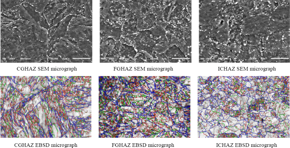
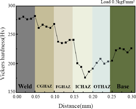
In the case of ICHAZ, partial dissolution of precipitates and coarsening of precipitates both are observed simultaneously. After the cooling, ICHAZ shows a complex structure of untempered lath martensite, retained over-tempered martensite, newly-formed PAGs, coarse tempered PAGs with newly formed fine precipitates and existing coarse precipitates along the new PAGs. Among them, the local area containing the retained over-tempered martensite within ICHAZ, should be subjected to one more tempering during PWHT. Hence, polygonal subgrains with lower density of dislocations are well-developed due to recovery, and more coarsened precipitates resulted from double tempering are present in ICHAZ. This microstructure evolution makes ICHAZ have the lowest hardness. Hong et al.30) investigated microstructure and hardness of RAFM steel weld produced by TIG. PWHT was conducted at 760 °C for 2hr. Fig. 5 shows HAZ microstructures of RAFM steel weld. It is clear that ICHAZ showed larger size of precipitates, wider lath width and smaller lath fraction, compared to CGHAZ or FGHAZ. These metallurgical factors lead to the softest hardness in ICHAZ (Fig. 6).
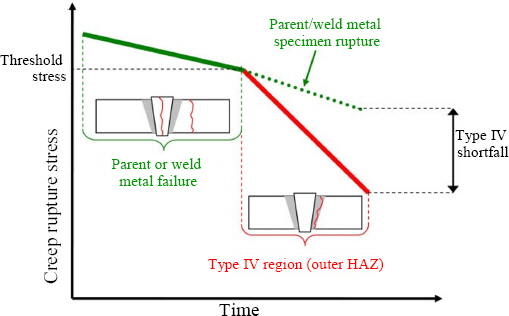
RAFM steels (including 9-12Cr heat-resisting steels) is susceptible to Type IV premature failure during long- term creep. This is a challenging issue which is believed to be difficult to overcome. Cracks are defined on the basis of their location in weldments. Localized creep cavitations in soft zone lead to intergranular fracture during the long-term creep exposure at low stress. This is termed as Type IV cracking occurred near HAZ boundary (Fig. 7). The carbide coarsening and partial dissolution of precipitates in FGHAZ and ICHAZ make it relatively soft compared to CGHAZ and weld zone.

Compared to creep failure (or rupture) in weld metal (Type I rupture) or base metal, when Type IV failure occurs, the actual creep life is much shorter than expected (see significant life difference in Fig. 8). It is disadvantageous in terms of stable operation and maintenance of the fusion reactor. Many studies have been made to elucidate the cause of type IV failure: grain refinement of FGHAZ32), HAZ softening and coarsening of M23C633,34), the formation of Laves phase31) and distribution of precipitates28,29) were proposed. Recently, Tsukamoto et al.28), Abe29) and Shin et al.26) claimed that lack of precipitation strengthening at PAG and block boundaries of FGHAZ could be the most dominant factor to cause type IV failure. As shown in Figs. 4(a) and (b), few precipitates were observed at the fine PAG boundaries of FGHAZ before creep. During creep at higher temperatures/lower stresses, creep damage would be accumulated more by diffusion process rather than by dislocation glide. Under this condition, most of strains could be localized at the grain boundaries by either strain concentration at the weak (or softest) grain boundaries or diffusion-mediated sliding of grain boundaries. This damage accumulation to grain boundaries could be the most significant at the FGHAZ which has the largest area of grain boundaries. Furthermore, this damage accumulation to the FGHAZ could be accelerated when the strengthening of grain boundaries by carbides is not facilitated26).
Therefore, in order to suppress the Type IV fracture of RAFM steels (including 9-12Cr heat-resisting steels), it is understood that a welding technology should be designed to reinforce carbide precipitation strengthening at grain boundaries (especially FGHAZ/ICHAZ). Several studies demonstrated that the Type IV fracture can be effectively suppressed, when PWHT includes normalizing followed by tempering28,29,35). This full PWHT makes HAZ microstructures be similar to that of base metal.
3. Microstructure Degradation and Welding Tech- nology Development
Tanigawa et al.36) conducted room-temperature tensile tests of Japanese RAFM steel F82H. They investigated the influence of irradiation effect (300°C, 5 dpa @ High Flux Isotope Reactor) on the tensile properties of base metal and TIG welded joints. When irradiated, the welded part and the base metal were hardened so that the tensile strength greatly increased and the elongation was significantly reduced. Even in the case of HAZ, the degree of hardening was low, indicating relatively low strength (Fig. 9).
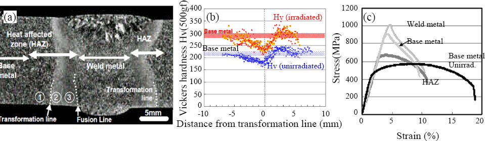
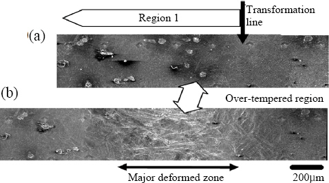
As already mentioned, ICHAZ (indicated by zone 1 in Fig. 9(a)) shows the softest hardness since it contains larger size of precipitates, wider lath width and smaller lath fraction. It is normal that the ICHAZ is the tensile-fractured position since most strains are localized at the softest zone during deformation. Hence, we have to minimize the width of ICHAZ as much as possible to induce homogeneous deformation.
Fig. 11 shows the comparison of creep lives between base metal and TIG welded joint of F82H. In the creep temperature range of 500-600 °C, the welds show a creep life that is not significantly inferior to the base metal. This is because the TIG welded joints in this range were all ruptured at the base metal, and thus exhibits a creep life close to base metal. However, when the stress is lower than 100 MPa at 650 °C, it can be seen that the Type IV fracture is clear, thereby significantly reducing the creep life.

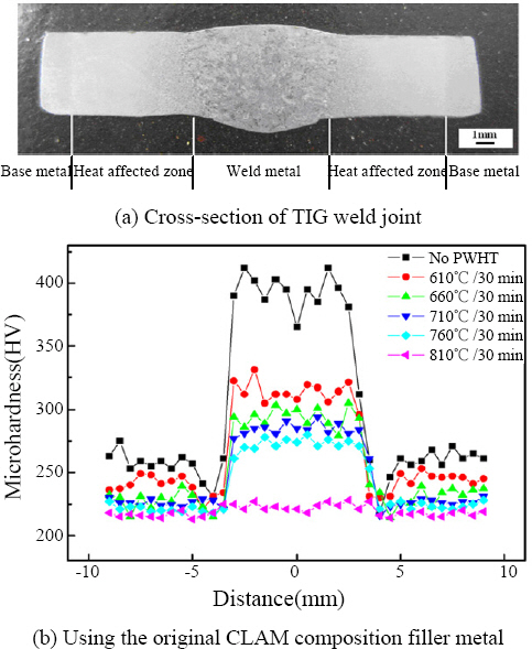
The weld HAZ of RAFM steels has a detrimental effect on the blanket stability because of the uneven distribution of hardness, the lowest hardness and the presence of FGHAZ which can cause Type IV failure during creep deformation. For this reason, it is essential to develop welding techniques to minimize the width of HAZ (especially FGHAZ) as much as possible. In the case of TIG welding, research and development are underway to control the heat input to avoid the generation of δ-ferrite in CGHAZ and to realize the optimum microstructure10). In addition, the development of filler metals for TIG welding is actively in progress11). The RAFM steels with tempered martensite have high hardenability so that fresh martensite is inevitably produced in welds immediately after welding. Thus, PWHT treatment must be performed. For this reason, PWHT optimization has been investigated to remove hardness non-uniformity in the HAZ12,28,29,35).
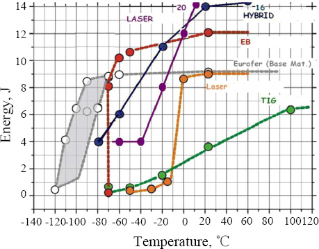
Research into applying a high density of energy heat source, such as laser or electron beam welding, has been actively conducted. As shown in Fig. 13, it can be seen that the ductile brittle transition temperature (DBTT) curve of the EB weld is much better than the TIG weld.
Sawai et al.15), who is affiliated with the Japan Atomic Energy Research Institute (JAERI), conducted a PWHT (720 ˚C/ 1hr/ air cooling) for TIG and EB beam welds using F82H. When optimizing the EB welding, it was confirmed that the weld width was very narrow and the sharp hardness decrease in ICHAZ/OTHAZ was hardly found, as seen in Fig. 14.

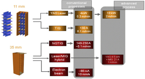
For this reason, in Europe, in addition to TIG welding, laser welding, laser-MIG hybrid welding, and EB welding are actively being applied to fabricate TBM by using European RAFM steel Eurofer97 (note Fig. 15).
4. Summary
The R&D status of welding processes suitable for RAFM steels was reviewed in terms of microstructure/ mechanical degradation in order to address the key technical issues, and finally to provide an insight how to develop the welding technology for improving the welds performance. Major conclusions derived are as follows:
1) Since the blanket is exposed to high flux of neutron and complex periods of fluctuating mechanical and thermal stresses, understanding of degradation behaviors of RAFM welds are needed to provide feedback for better development of welding processes.
2) The degradation of the RAFM steel welds originates from matrix recovery associated with lath widening and reduction of dislocation density, coarsening of precipitates and formation of Laves and Z phases.
3) In the welds of RAFM steels, FGHAZ and ICHAZ are highly susceptible to Type IV cracking. Localized creep cavitations in soft zone lead to intergranular fracture during the long-term creep exposure at low stress.
4) For this reason, it is essential to develop welding techniques to minimize the width of HAZ (especially FGHAZ) as much as possible. A high density of energy heat source, such as laser or EB welding, has been actively conducted, and will be more applied to guarantee a higher safety of blanket modules.
5) PWHT optimization has been investigated to remove hardness non-uniformity in the HAZ. Enhanced HAZ strengthening approach will be designed to obtain excellent microstructures, which is a highly resistant to Type IV failure.
Acknowledgement
This research was supported by Changwon National University in 2019∼2020.