Trend of Resistance Spot Welding Technology of Al-Si Coated Hot-Stamped Boron Steel for Automobile Body
자동차 차체용 Al-Si 도금된 핫스탬핑 보론강의 저항 용접 기술 동향
Article information

Abstract
As environmental regulations have been tightened around the world, domestic and foreign automobile industries are increasing the proportion of hydrogen and electric automotive components using lightweight materials to reduce exhaust gas emissions and improve fuel efficiency. In particular, hot-stamped boron steel is being used as an alternative material for frame weight reduction due to thickness reduction, excellent workability, and good elongation. However, surface coating is essential to prevent surface decarburization phenomena and oxidation scale formation between hot stamping processes of boron steel. The coating layer causes many problems in the weldability such as a narrow weldable current range and deterioration of mechanical properties during resistance welding. Therefore, in this study, we introduce research performed to improve the weldability of Al-Si coated hot-stamped boron steel in terms of the material and process.
1. Introduction
With environmental regulations being reinforced around the world in recent years, the domestic and foreign automobile industries are increasing the proportion of hydrogen and electric vehicle parts using lightweight materials to reduce exhaust gas emissions such as hydrocarbons and carbon dioxide and to improve fuel efficiency1,2). In order to reduce the weight of the automobile body, materials for exterior body parts such as bumpers and bonnets are replaced with carbon fiber reinforced plastic (CFRP) and aluminum alloy, whereas A-pillar and B-pillar, directly related to passenger safety, are replaced with ultra-high-strength steel1,3,4).
Types of ultra-high strength steel include twinning induced plasticity (TWIP), transformation-induced plasticity (TRIP), and dual-phase (DP) steel. In particular, hot-stamped boron steel with a tensile strength of 1.5 GPa or higher is being used as an alternative material to achieve car body weight reduction with reduced thickness as well as excellent workability and elongation3,5). Hot-stamped boron steel is obtained by austenitizing boron steel with excellent hardenability at a high temperature of 850-950 ℃ or higher for 4-6 minutes, followed by a hot stamping process involving simultaneous molding and quenching for 6-10 seconds1). In order to prevent problems such as surface oxidation, foreign substances, and decarburization from occurring in a high-temperature environment, the surface of boron steel is subjected to hot-dip galvanization or Al-Si coating prior to the hot stamping process1,6,7).
The welding process is essential for applying hot- stamped boron steel to an automobile body, where various problems in resistance welding, accounting for more than 80% of the body assembly process, need to be solved. Previous studies have reported that hot- stamped boron steel has a narrower weldable current range compared to mild steel or high-strength steel, with degraded mechanical properties due to the softened structure in the weld zone8-10). Furthermore, hot- stamped galvanized boron steel is associated with liquid metal embrittlement during resistance welding, while the ZnO oxide layer causes local heating11-13). On the other hand, it has been reported that liquid metal embrittlement does not occur in Al-Si coated hot- stamped boron steel, which also demonstrates adequate weldability14). The Al-Si coating layer, however, requires improvement in weldability due to the oxide layer on the outermost surface, the thick alloying layer, and the high rigidity of the material3,6).
Recently, research is being conducted with a focus on the materials and processes to improve weldability during resistance welding of Al-Si coated hot-stamped boron steel. In terms of material, the welding properties can be partially improved by removing the coating layer on the surface through mechanical polishing or chemical etching, but the removal of the coating layer on the surface of the material may lead to corrosion, while adding the coating layer removal process to the production line degrades productivity. Meanwhile, there have been studies attempting to make an improvement in terms of material by controlling the structure of the intermetallic layer through the optimization of the hot stamping process conditions7). In terms of process improvement, a method to improve welding quality by controlling the welding waveform is reported as a practical alternative with high field applicability15). Therefore, this study aims to introduce the research on improving weldability of Al-Si coated hot-stamped boron steel by controlling the coating layer during resistance welding, in terms of material and process.
2. Resistance Welding Characteristics of Al-Si Coated Hot-stamped Boron Steel
2.1 Weldability of Al-Si coated hot-stamped boron steel
The weldability during resistance welding for each type of plate is generally evaluated by the weldable current range, which indicates the range from the minimum weld current that satisfies the nugget diameter or button diameter (e.g., 4√t or 5√t, t=plate thickness) to the maximum weld current before the occurrence of expulsion16). Fig. 1 shows the weldable current range of mild steel, dual-phase (DP) steel, and Al-Si coated hot-stamped boron steel. Al-Si coated hot-stamped boron steel produces nuggets faster due to its high contact resistance (complex intermetallic layer and oxide layer), high volume resistance (addition of high alloyed elements), and high rigidity compared to other steels. Therefore, expulsion occurs in the low current section, resulting in a narrow weldable current range3,8). With a narrow weldable current range, expulsion occurs randomly even under conditions that would not induce expulsion, causing deterioration of weldability and welding quality20).
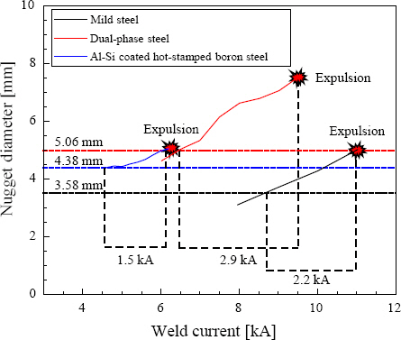
Fig. 2 shows the change in resistance about the change in electrode-force on the presence or absence of the Al-Si coating layer of hot-stamped boron steel. The overall resistance decreased linearly as the electrode-force increased. In the presence of the coating layer, the overall resistance decreased despite the increase in the electrode-force compared to the condition without the coating layer, but the difference in resistance remained. In other words, the increase in the resistance is caused by the coating layer (intermetallic layer), and even if the electrode-force is increased, there is a limit to the decrease in the resistance value. This is due to Si, a component of the coating layer, having a higher electrical resistance than Fe, resulting in the formation of intermetallics, such as Fe-Al and Fe-Al-Si, with higher resistance than Fe, during austenitizing8,22). Therefore, the Al-Si coating layer acts as a cause of high heat generation during resistance welding, thereby increasing the occurrence frequency of expulsion6,13,17). When metal particles are attached to the surface due to expulsion, it causes various problems, such as deterioration of coating quality and reduced productivity. As the molten metal of the base material is discharged to the outside of the nugget due to expulsion, pores are formed in the center of the nugget, deteriorating the mechanical properties5,23,24). Therefore, a process capable of controlling the Al-Si coating layer seems necessary in order to improve the welding characteristics by reducing expulsion.

Fig. 3 shows the results of comparing the size of the nugget diameter and mechanical properties according to the presence or absence of a coating layer. The nugget diameter and cross-tension strength increased as the weld current increased regardless of the presence or absence of the coating layer. Under the same current condition, the nugget diameter was slightly larger in hot- stamped boron steel with a coating layer due to high heat generation, but its cross-tension strength was about 10-40% lower. When the Al-Si coating layer remains in the corona bond zone (outer part) during resistance welding, it is reported to act as a notch between tensile tests and break early against the concentrated stress, thereby affecting the strength21,23).
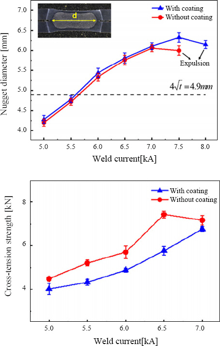
Fig. 4 shows the temperature distribution of the weld zone and the microstructure of the weld zone about the weld time during resistance welding through the simulation program. Martensitic structures are observed in the coarse-grained heat affected zone (CGHAZ) and the fine grain heat affected zone (FGHAZ) heated to solidus temperature, whereas ferrite and martensite coexist in the inter-critical heat affected zone (ICHAZ) heated to the austenite phase transformation temperature (A3). Tempered martensitic structures were observed in the sub-critical heat affected zone (SCHAZ) heated at a lower temperature.
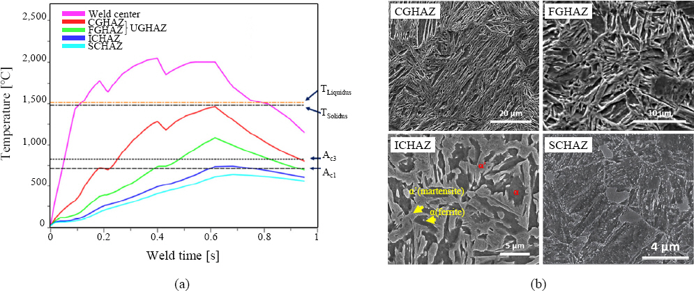
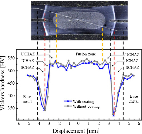
Fig. 5 shows the Vickers hardness distribution in the weld zone of Al-Si coated hot-stamped boron steel. As a result of comparing the microstructure shown in Fig. 4 with the hardness distribution, the correlation between the microstructure and mechanical properties in the weld zone can be confirmed. While the upper-critical heat affected zone (UCHAZ) and ICHAZ exhibit higher hardness than the base metal, SCHAZ exhibits hardness that is about 26% lower than the base metal. Some studies pointed out that δ-ferrite was precipitated in SCHAZ and the mechanical properties of the weld zone deteriorated9,10). In other words, the molten material is pushed into the corona bond zone due to the difference in the thermal expansion coefficient and the melting point of the coating layer component. Accordingly, in SCHAZ having a thermal history below the temperature at which ferrite and cementite are formed (Ac1), fusion boundary softening composed of the δ-ferrite phase and tempered martensite structure occurs, decreasing the Vickers hardness26).
2.2 Trend of weldability improvement in terms of material
The Al-Si coating layer of hot-stamped boron steel is formed in the form of a complex intermetallic compound as Fe of the base material diffuses into Al and Si, which are components of the coating layer, during austenitizing near temperature A325). Therefore, the composition and thickness of the intermetallic layer in the coating layer can be controlled by combining variables such as the temperature, temperature increase rate, and time of the heat treatment.
Fig. 6 shows the cross section of the coating layer with improved weldability during resistance welding and the cross section of the coating layer without. Fe and Al are combined in the superficial layer and the intermediate layer, and Fe, Al, and Si are combined in the Al-rich intermetallic layer and the interdiffusion layer28). The coating layer with improved weldability was consisted of a superficial layer, an Al-rich intermetallic layer, an intermediate layer, and an interdiffusion layer in the order of the outermost layer to the innermost layer, with the Al-rich intermetallic layer forming a continuous layer. The coating layer with poor weldability is composed of an island type Al-rich intermetallic alloy layer and an interdiffusion layer28,29). In other words, there are differences in the interlayer composition of the coating layer and the shape of the Al-rich intermetallic layer.

Although the cause of the improved weldability has not been clearly elucidated, the Al-rich intermetallic layer and the superficial layer have been reported to affect the resistivity of the coating layer with the influence of its unique properties and roughness28). Furthermore, the contact resistance increases when an intermetallic bonded with Fe and Al is present30,31). Therefore, the weldability seems to have improved due to the influence of the superficial layer and the Al-rich intermetallic layer on the flow of current, surface heating, and nugget formation in the early stages of resistance welding28). The shape of the Al-rich intermetallic layer is controlled by the temperature increase rate during austenitization heat treatment. When the temperature is raised by 30 ℃/sec to 930 ℃, a continuous alloying layer can be created, and when the temperature is raised by 10 ℃/sec, an island-shaped alloying layer is formed 7,32,33). In the future, it will be necessary to investigate the cause of the improved weldability depending on the shape of the intermetallic layer.
Fig. 7 shows the cross section of the hot-stamped boron steel (30MnB5) on the austenitizing heat treatment temperature and the EDS analysis result. The Al content was distributed highly throughout the outermost layer to the base material before heat treatment, with an inhibition layer made of Al, Si, and Fe being formed. The inhibition layer serves to suppress the rapid reaction of Fe in the base material to the coating layer, but the inhibition layer disappears during the heat treatment, while Fe from the base material diffuses into the coating layer to form a diffusion layer22). When heat treatment is performed at a relatively high temperature, the degree of alloying by diffusion increases27). Therefore, a diffusion layer with a thickness of about 5 ㎛ was formed during austenitizing at 850 ℃, but a diffusion layer with a thickness of 10 ㎛ was formed through heat treatment at 950 ℃.
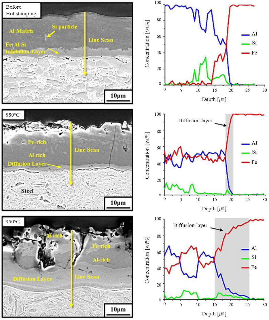
Fig. 8 shows the dynamic resistance curve and weldable current range on the austenitizing temperature to compare weldability with respect to the thickness of the diffusion layer. In Fig. 8 (a), the coating layer melts and exhibits similar behavior as the weld time increases, despite slight differences in the dynamic resistance of the initial contact due to the influence of the coating layer3). Fig. 8b shows the weldable current range according to austenitizing. The weldable current range was about 1.8 kA under the 850 ℃ heat treatment condition, whereas a weldable current range was not ensured under the 950 °C heat treatment condition. In other words, it is reported that due to the thick diffusion layer formed under the 950 ℃ heat treatment condition, expulsion occurs even at low weld current, exhibiting poor thermal welding characteristics22).

Combining the results of two studies evaluating the weldability according to the temperature increase rate and the heat treatment temperature for austenitizing hot-stamped boron steel, it seems possible to improve weldability through control of the coating layer in terms of material by inducing the formation of a continuous Al-rich intermetallic layer in the coating layer or optimizing the hot stamping process conditions to minimize the reduction in the thickness of the diffusion layer.
2.3 Trend of weldability improvement in terms of process
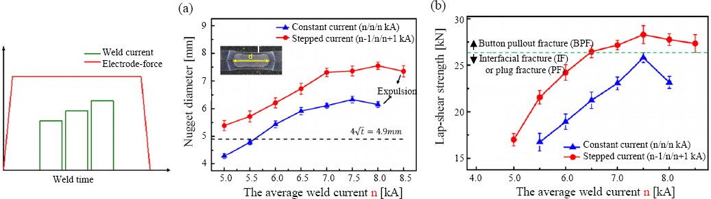
In terms of material, weldability was improved by controlling the composition of a specific layer in the coating layer, but problems such as mixing of foreign substances and uneven thickness of the coating layer may occur frequently during the manufacturing of hot-dip coated steel. In addition, it may be difficult to control the coating layer due to various environmental factors in the heat treatment process. Accordingly, there has been recent research on the technology to control the melting behavior of the coating layer in order to improve weldability in the manufacturing process of hot-stamped materials9,15,26,35). This is a method of optimizing welding characteristics through process variable control during resistance welding, with the electrode-force, the weld current, and the weld time as variables. A typical example is a technique for controlling the waveform of the welding current that controls the weld current and the weld time. Fig. 9 shows the types of welding current waveform control according to weld time. Fig. 9 (a) is the one-step pulse waveform control that applies a continuous current, and Fig. 9 (b) is the two-step pulse waveform control condition for controlling the weld current including the pre-pulse in the form of a pulse. As for the two-step pulse welding current waveform control condition, unlike in one-step pulse welding current waveform control, two or more pulses with controlled weld current and weld time are applied, where each pulse serves a distinguished role, with the first pulse for controlling or removing the coating layer and the second pulse for the main welding to generate nuggets.
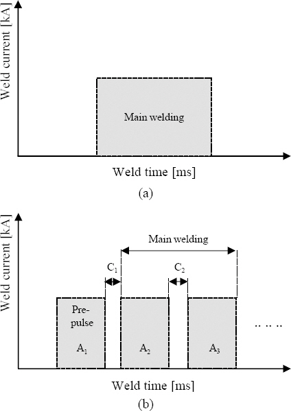
(a) traditional weld schedule(1-step), (b) weld schedule of pulse-control
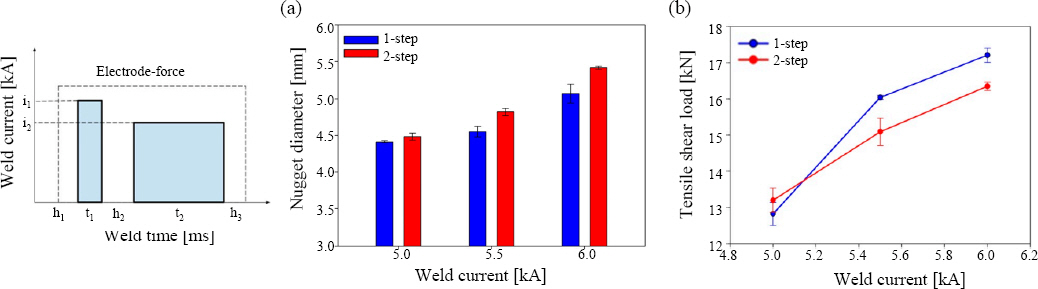
Fig. 10 shows the results of comparing the nugget diameter and tensile shear load of one-step pulse welding current waveform control and two-step pulse welding current waveform control. When applying two-step pulse welding current waveform control at the same welding current, the nugget diameter was larger than that produced by one-step pulse welding current waveform control. As for the tensile shear load, one-step pulse welding current waveform control with a relatively small nugget diameter had a higher tensile load than two-step pulse welding current waveform control, and there was a difference in fracture shape as well (Fig. 11).
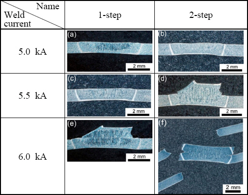
While the mechanical strength of interfacial fracture (IF) is known to be lower than that of button pullout fracture (BPF) in general, the opposite results were obtained in the fracture mode of two-step and one-step pulse welding current waveform controls9,36). This is because ferrite was formed in the partially melted zone and the fraction of the relatively softened area increased22). During resistance welding, the nugget has a high solidification rate, allowing insufficient time for solute atoms with a low melting point to dissolve into the matrix, and segregation is observed in the weld zone37). It is reported that the amount of ferrite and carbide produced increases when segregation occurs, with lowered mechanical properties as such a region exists as a weak part38). Therefore, in the relationship between the known fracture mode and mechanical properties, it is necessary to optimize the process by considering the microstructural aspect as well36,39).
Fig. 12 shows the results of comparing the weldability of constant and stepped pulse conditions. As a result of comparing the constant pulse condition and the stepped pulse condition, in which the weld current is increased step by step, the weldable current section is 3.0 kA or more with the stepped pulse current control, demonstrating superior weldability compared to the constant current condition (Fig. 12 (a)). As a result of comparing the shear strength in Fig. 12 (b), a sufficient nugget diameter was secured to cause BPF under the welding condition of 6.5 kA by the stepped pulse welding current waveform control. According to Joule’s law, a large difference seems to have occurred in the size of the nugget diameter and the resulting tensile load due to heat input control under the stepped pulse condition rather than the constant current pulse welding current waveform control26).
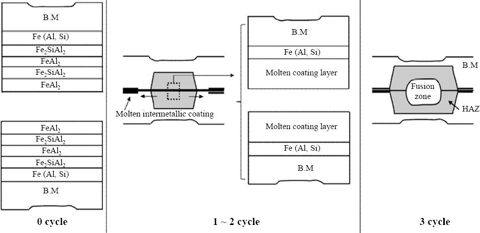
Combining the pulse welding current waveform control conditions introduced in Section 2.3, the welding characteristics were improved by maximally increasing the nugget diameter with a reduced influence of the Al-Si coating layer, using processes such as pre-pulse and stepped pulse controls to apply current prior to the main welding. Fig. 13 shows the melting behavior of the coating layer during resistance welding of Al-Si hot-stamped boron steel to comprehend the principle of pre-pulse welding current waveform control. In the initial stage of heat input, the Al-Si coating layer is melted from a solid phase to a liquid phase, and the molten coating layer is pushed in the direction of the plate material interface due to the electrode-force3). Through waveform control such as pre-pulse control, process conditions that can push the coating layer toward the outside should be secured, and then the contact area should be secured. This aims to secure the contact area as much as possible while minimizing the contact resistance by pushing the coating layer of the joint to the outer side as much as possible to induce the effect of removing the coating layer35). Such behavior of the coating layer is also observed in projection welding6). As a result, various research results have been reported to improve welding characteristics through pulse welding current waveform control during resistance welding of Al-Si coated hot-stamped boron steel, which calls for in-depth discussion when setting the welding process and conditions in the future.
3. Conclusion
The research aimed at improving weldability during resistance welding of Al-Si coated hot stamped boron steel are summarized and reviewed in terms of material and process.
1) During resistance welding of Al-Si coated hot-coated boron steel, it has a narrow weldable current range compared to other steels owing to the components of the coating layer having a higher resistance than Fe. Furthermore, mechanical properties are deteriorated by the coating layer remaining in the notch of the sheet/ sheet interface during welding or the softened area owing to the generation of ferrite in the partially molten portion near the molten line.
2) In terms of material, weldability can be improved by inducing the formation of a continuous Al-rich intermetallic layer in the Al-Si coating layer by optimizing the process variables such as the temperature increase rate between austenitizing heat treatments and heat treatment temperatures and by controlling the thickness of the diffusion layer to under 5 ㎛.
3) In terms of process, the weldability can be improved by controlling the waveform to apply pre-pulse. The initial pre-pulse pushes out the Al-Si coating layer, minimizing the influence of the coating layer, to let the subsequent pulse induce the formation and growth of nuggets, thereby improving the weldable current range and mechanical properties compared to one-step pulse welding current waveform control under the same welding conditions. With the two-step welding current waveform control, there is a problem in that the mechanical properties decrease due to the increase in the softened area due to the generation of ferrite. On the other hand, the three-step pulse welding current waveform control that gradually increases the weld current secures the contact area at the first pulse, gradually inducing the growth of the nugget to secure a weldable current range of 3.0 kA or more and increasing the mechanical properties by up to 40%.
Acknowledgment
This research was carried out with the support of a project (20013403) implemented by the Ministry of Trade, Industry and Energy.