Warning: fopen(/home/virtual/kwjs/journal/upload/ip_log/ip_log_2024-05.txt): failed to open stream: Permission denied in /home/virtual/lib/view_data.php on line 88 Warning: fwrite() expects parameter 1 to be resource, boolean given in /home/virtual/lib/view_data.php on line 89 Mechanical Properties of Fe-TiC Composites for Friction Stir Welding Tool Application by a Spark Plasma Sintering

J Weld Join > Volume 42(2); 2024 > Article
Park, Yang, and Park: Mechanical Properties of Fe-TiC Composites for Friction Stir Welding Tool Application by a Spark Plasma Sintering

Abstract

TiC, which has high hardness, was added to reinforcing material to improve the mechanical property of Fe. Fe-TiC composites as a function of TiC contents were fabricated by high energy ball milling and spark plasma sintering. The Fe-TiC composites were synthesized with different TiC contents (5, 10, and 20 wt.%) and subsequently consolidated by rapid sintering at 850°C under 60 MPa. The relative density of Fe-TiC composites is from 99.5% to 94% as the TiC contents increased. Due to the increased in TiC contents, which contributes to the sintering rate with low wettability and low deformation at high temperature, has resulted in a decrease of relative density. The hardness of Fe-TiC was ranged from 128.9±10.4 to 687.2±14.6 kg/mm2 as the TiC contents increased. Particularly, the highest hardness of TiC weight percent was 20 wt.% TiC which was related with Hall-Patch relationship. Also this enhancement was attributed to the dispersion strengthening effect of the agglomerated powders and solid solution strengthening through high energy ball milling. Microstructure, and phase analysis of Fe-TiC composites were investigated.

1. Introduction

Many studies have been conducted on the lightweight technology of various transport vehicles, such as aircraft, railway vehicles, and ships, in terms of ecofriendly material development and energy saving. To bond these lightweight and high-strength materials, friction stir welding (FSW), a non-melting solid-state welding technology that utilizes a tool rotating at high speed, has been used1). FSW technology is known as a next-generation welding technology that is applied to the welding of the same and heterogeneous materials of lightweight materials (e.g., Al and Mg) or high-melting point materials (e.g., stainless steel, Ti, and nickel base alloys). The development of long-life tool materials is important for the welding of low- and high-melting point materials, and research has been conducted on various materials with high wear resistance, toughness, and strength2,3). WC-Co has been commonly used as a tool for FSW, but the ionization of Co and surface corrosion at the frictional heat of more than 400°C decrease the tool life. In addition, due to the machinability and cost problems, research has been conducted on alternative materials. Metal matrix composites (MMCs) used as alternative materials improve the performance and efficiency of the product by adding transition metal carbides to the metal matrix. They can also reduce manufacturing costs and exhibit high strength, stiffness, and wear resistance.
Initial raw material synthesis methods that are used to produce MMCs include chemical and mechanical synthesis methods. Chemical synthesis methods include the combustion synthesis method4) and carbothermal reduction method5) while mechanical synthesis methods include stirred ball milling (atritor)6) and high energy ball milling (HEBM)7,8). Particularly, HEBM has been commonly used in the production of metal-carbide-based composites as it improves mechanical properties by uniformly distributing particles and yielding nano- particles through the induction of high energy states with collisions between particles. Metal-carbide-based composites include Ni-WC9), Ni-TiC10), and Fe-TaC11). Conventional sintering methods include hot pressing (HP)12), pressureless sintering (PLS)13), and hot isostatic pressing (HIP)14). As they are external indirect heating methods, however, long-term sintering induces uneven internal/external properties and reduces mechanical properties due to particle growth.
This study aimed to evaluate the mechanical properties of Fe-TiC composites, which are considered substitutes for WC-Co as FSW tool materials. After synthesizing Fe-TiC composite powder through the HEBM process, a high-density sintered body was produced by applying the spark plasma sintering method (SPS)15,16). The mechanical properties of the Fe-TiC composites were improved as the TiC content increased. This appears to be due to the dispersion reinforcement and Fe particle growth inhibition effects of TiC.

2. Experimental Method

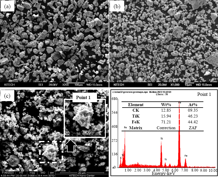
Fe powder (Yuelong metal powder Co. Ltd, ~44 μm, purity 99.5%) and TiC powder (Alfa, LTD, ~5.0 μm, purity 99.5%) were used as initial raw material powders. Fig. 1 demonstrates the results of analyzing microstructures using a scanning electron microscope (SEM, JSM-7001F, JEOL) to observe the geometry of the initial powders. Fe and TiC have irregular angular shapes. As shown in Fig. 1(c), the Fe-TiC (Mechanical Alloyed, MAed) phase is a mechanical alloy phase by HEBM in which TiC is aggregated to Fe.
Fig. 1
Micromorphology of (a) Fe, (b) TiC raw powders, (c) Fe-10wt.% TiC composite by planetary ball milling, and (d) point 1 of Fe-10wt.% TiC composite
jwj-42-2-206-g001.jpg
5, 10, and 20 wt% of TiC were added based on the 100 weight of Fe powder, and the HEBM process was performed. For ball milling, stainless steel balls were used. The weight ratio between the balls and the powder was 10:1. They were sealed in a reinforced stainless steel container and subjected to mixing and grinding for nine hours at a speed of 250 RPM. Process control agents (PCA) (ethanol) were added for the uniform mixing of Fe and TiC with a large density difference, and the weight ratio of the powder and PCA was set at 100:1. Upon the completion of the process, the mixture was dried for 24 hours using a vacuum oven. When the particle size of the mixture powder was analyzed using a particle size analyzer, it was found that the average particle size decreased to 4.22, 4.06, and 3.02 μm as the TiC content increased. This seems to be because the brittle powder (TiC) crushing effect was reinforced as the TiC content increased.
A graphite mold (outer diameter: 30 mmØ, inner diameter: 10 mmØ, height: 40 mmT) was filled with the produced powder. The upper and lower parts were blocked with graphite punch. The sealed graphite mold was installed in a spark plasma sintering device (SPS 9. 40 MK-III, Sumitomo Heavy Industries), and a vacuum condition of approximately 6 Pa was formed. After applying a sintering pressure 60 MPa, the internal temperature of the graphite mold was measured using a K-type thermocouple. The mixed powder of Fe-TiC was heated to 500°C at a heating rate of 60°C/min, and then heated to the final target temperature of 850°C at a heating rate of 40°C/min. During cooling after sintering, the applied pressure was removed at 600°C.
The density of the prepared specimen was measured using the Archimedes method. To observe the surface of the sintered body, the surface was corroded for approximately five to ten seconds using a Nital solution (1-5% Nitric acid (HNO3) + 99-95% Alcohol (CH3OH)). After the surface corrosion, the microstructure of the sintered body was analyzed using SEM, and the average grain size was measured using the ImageJ software. In addition, the phases of the powder after milling and the sintered body were analyzed through X-ray diffraction (XRD, PIXCEL 1DDETERCTOR, Panalytical). Among the mechanical properties, hardness was evaluated using a Vickers hardness tester (HV-100, Mitutoyo) by maintaining a load of 20 kgf for 15 seconds. The elastic modulus was evaluated using the indentation mark of the specimen by maintaining a load of 2 kgf for ten seconds using nanoindentation (HM 2000, Helmut Fischer).

3. Experiment Results and Discussion

3.1 Analysis of the sintering characteristics of Fe-TiC using the spark plasma sintering method

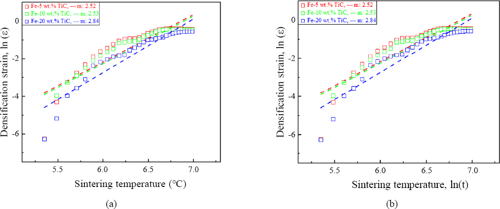
Fig. 2(a) shows the shrinkage rates of the Fe-TiC composites according to the sintering temperature and Fig. 2(b) the densification strain. Shrinkage began from approximately 200°C, and sintering was completed at 850°C. The shrinkage rate change of Fe-TiC can be explained in four sections17), and B, C, and D represent Fe-5 wt.%TiC, Fe-10 wt.% TiC, and Fe-20 wt.% TiC, respectively. In the early stages (B1, C1, and D1), approximately 3 to 5% of shrinkage occurred compared to the green body. A slight density increase in the second stage (B2, C2, and D2) is due to the viscous flow mechanism caused by localized deformation between the Fe particles. In the third stage, bulk deformation occurred due to the rapid shrinkage (B3, C3, and D3). The shrinkage rate of Fe-20 wt.% TiC was significantly lower than that of Fe-5 wt.% TiC. This is because the Fe content that contributes to shrinkage decreased due to the low wettability of TiC and the material with low deformation at high temperature. In the final stage (B4, C4, and D4), the shrinkage rate decreased due to the removal of residual pores and particle growth by high activation energy. Fig. 2(b) compares the sintering behavior according to the TiC content, which is related to densification and reinforcement behavior during the sintering process, using equation (1)18).
(1)
εsm=(L/L0)m=kt/T
where εs is the densification strain, m is the sintering index, ΔL is the macroscopic shrinkage length change, L0 is the length of the green body, K is the sintering constant according to the temperature (K (T)), t is the isothermal time, and T is the temperature maintained.
The change in sintering index (m) in the sintering temperature range that showed rapid shrinkage behavior (approximately 200 to 700°C) was calculated according to Ɛs. According to equation (1), the magnitude of macroscopic shrinkage decreases as m increases. This means that the diffusion path decreases in the lattices between particles and at particle interfaces. Consequently, the difference in “m” depending on the TiC content indicates that sliding at particle interfaces affects densification during the residual pore removal process. It was determined that Fe-20 wt.% TiC (m = 2.84) with high m had relatively low relative density under high activation energy due to the continued removal of residual pores and solid diffusion that was not fully completed in the final sintering section19). Therefore, as the TiC content increased, the relative density of the produced sintered body tended to decrease to 95.2, 94.8, and 94.0%.
Fig. 2
Sintering behavior as a function of sintering temperature of Fe-TiC composites, (a) shrinkage rate and (b) densification strain
jwj-42-2-206-g002.jpg
In Fig. 3(a), a Fe1.95Ti0.05 solid solution peak20) was found between ductile and brittle powders by HEBM in addition to Fe and TiC peaks. Fig. 3(b) shows the XRD analysis results for the produced sintered body. The TiC1-x and Fe3C phases were additionally found. The carbon deficient (TiC1-x) phase indicates the occurrence of lattice defects and carbon deficiency during the recrystallization of TiC, and it is judged that the Fe3C phase was created by the rapid spread of C atoms to Fe21). The change in Gibbs free energy (ΔG) for the possible reaction (Fe3C) in the production process of Fe and TiC composites can be expressed as a temperature function22).
(2)
3Fe(α)+C(s)Fe3C(s),G1=38.05+0.446T(432912C)
According to the equation (2), the result of calculating the Gibbs free energy (ΔG) for the Fe3C generation reaction at 850°C is ΔG1 = -0.14 kJ/mol. This means that the phase is stable at 850°C. According to a study by Fang, only Fe3C was generated at temperatures above 740K23). Stokes and Wilson’s equation (3) was used to obtain the crystallite size, micro-strain, and lattice parameter, and the results are shown in Table 1.
(3)
b=bd+be=kλ/(dcosθ)+4εtanθ
where b is the full width at half maximum (FWHM) of the mechanical calibration value of the diffraction peak, and bd and be are the measurements of the internal stress reduction and FWHM, respectively. K is the Scherrer constant (0.9), and λ is the wavelength of the X-ray (CuKα, λ = 0.154 nm). In addition, d and ε are the particle size and micro-stress, respectively. θ is Bragg’s angle.
Fig. 3
The XRD patterns of Fe-TiC composites, (a) HEBMed powders and (b) SPSed compacts
jwj-42-2-206-g003.jpg
Table 1
Average result of Fe-TiC composites peaks measured by XRD
Specimens Crystallite size (nm) Micro strain (%) Lattice parameter (nm)
Fe-5 wt.% TiC 40.82 1.91 0.29
Fe-10 wt.% TiC 38.49 1.88 0.29
Fe-20 wt.% TiC 34.89 2.16 0.28
In Table 1, the average crystallite size decreased from 40.82 to 34.89 nm. This seems to be because TiC inhibited crystallite growth due to the Zener pinning effect according to S. Suwanboon et al.24). In addition, as stress increased from 1.91 to 2.16, the lattice parameter decreased from 0.29 to 0.28 nm. This appears to be due to the high compressive stress between the atoms caused by the collision between Fe and TiC particles during HEBM25). Therefore, it is expected that the hardness will be improved by the Zener pinning effect caused by the inhibition of crystallite growth and solid solution strengthening that involves compressive strength in the lattice.

3.2 Fe grain growth control and microstructure analysis

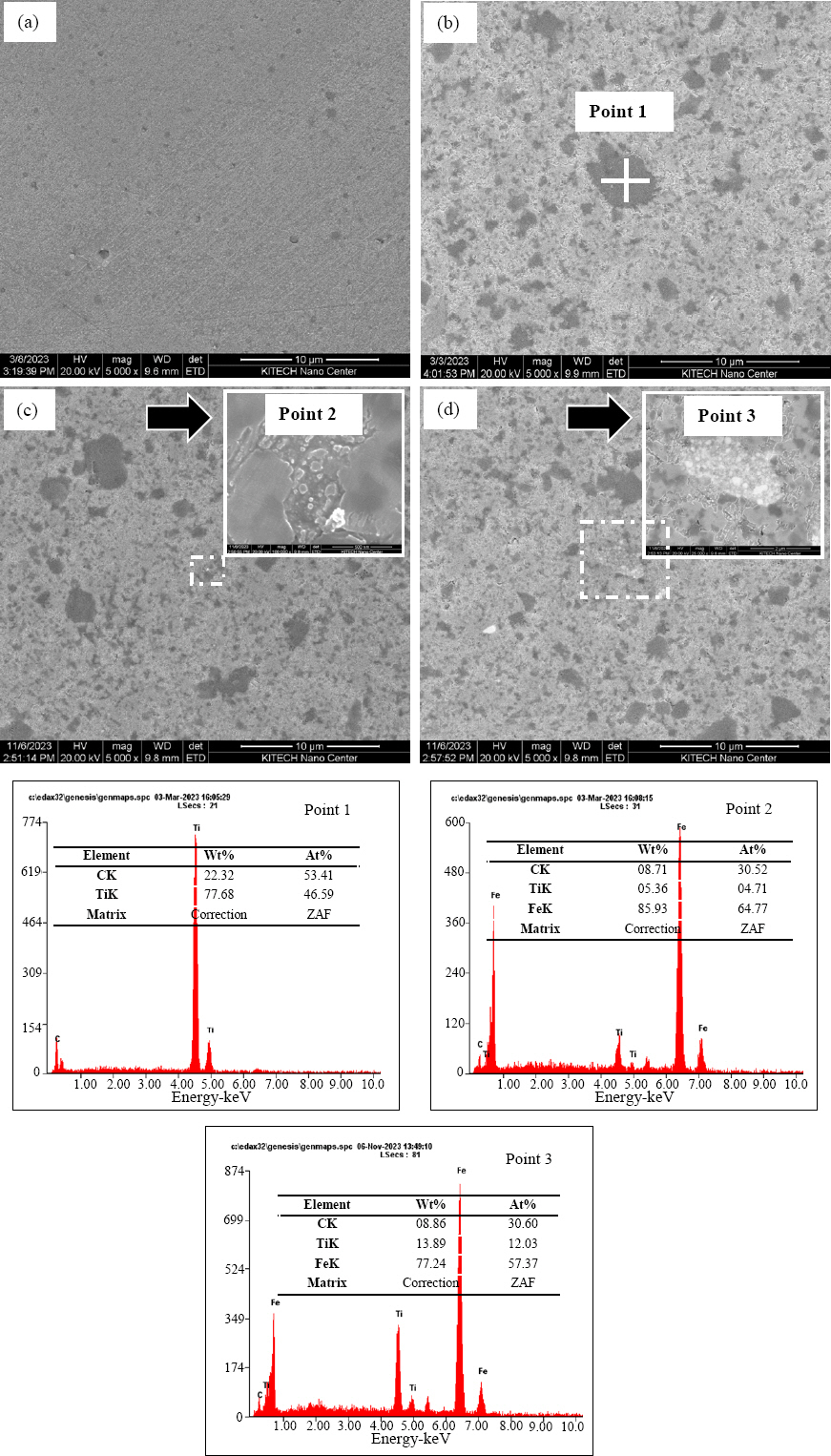
Fig. 4 shows the microstructure analysis results for the sintered body. TiC (dark grey) is uniformly distributed within the Fe matrix (grey). Fig. 4(d) shows that some fine TiC particles are embedded in the Fe matrix. They were found to be the MA phase generated by HEBM using EDX. The grain size of each composite was measured using the microstructure images and the linear analysis method (Image J). The results were 5.13, 4.61, 4.28, and 3.32 μm for 0, 5, 10, and 20 wt.% TiC, respectively. Fe grain growth was inhibited as the TiC content increased. This seems to be because particle rearrangement and grain boundary diffusion were accelerated as TiC formed stable interfaces with high interfacial energy. In other words, it is determined that the difference in Fe/TiC interfacial energy had a significant impact on grain growth behavior26,27).
Fig. 4
The SEM images after sintered at 850°C, (a) Fe, (b) Fe-5 wt.% TiC, (c) Fe-10 wt.% TiC, and (d) Fe-20 wt.% TiC
jwj-42-2-206-g004.jpg
Fig. 5 shows the distribution of TiC in the Fe matrix obtained through SEM-EDX mapping. As the TiC content increased, Fe and TiC were uniformly mixed and sintered by HEBM. In other words, TiC was distributed in the Fe matrix as reinforcement, and TiC was evenly distributed without aggregation by HEBM as its content increased28).
Fig. 5
The SEM-EDX images after sintered at 850°C, (a) Fe-5 wt.% TiC, (b) Fe-20 wt.% TiC
jwj-42-2-206-g005.jpg

3.3 Evaluation of the mechanical properties of the produced Fe-TiC composites

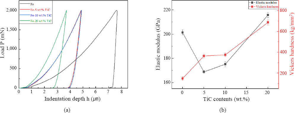
Fig. 6 provides the results of evaluating mechanical properties for each content. The average hardness and elastic modulus of each sintered body were obtained using equations (4) and (5), and the results are shown in Table 2.
(4)
Hv=kP/d2
where d is the diagonal length of the indentation mark, K is the constant related to the geometry of the indenter (1.89 x 10⁵), and P is the applied load.
(5)
Eeff=sπ/2βA
where Eeff is the effective elastic modulus between the specimen and the indenter, β is the form factor of the indenter (1.034), S is the stiffness at the time of load application, and A is the projected contact area pressed in the specimen surface.
Fig. 6
(a) Load p according to depth for elastic modulus, (b) Mechanical property of Fe (pure), Fe-5, 10, and 20 wt.% TiC sintered-bodies
jwj-42-2-206-g006.jpg
Table 2
Comparison of mechanical properties of Fe and Fe-TiC sintered body
Specimens Hardness (kg/mm2) Elastic modulus (GPa) Grain size (㎛) Relative density (%)
Fe 148.0±16.2 201.0±2.1 5.13 99.5
Fe-5 wt.% TiC 364.5±16.8 168.9±1.2 4.61 95.2
Fe-10 wt.% TiC 375.8±18.1 175.2±2.1 4.28 94.8
Fe-20 wt.% TiC 687.2±25.0 215.8±2.4 3.32 94.0
The hardness increased as the TiC content increased, and Fe-20 wt.% TiC exhibited the highest hardness value (687.2±14.6 kg/mm2) due to the dispersion reinforcement effect by TiC and the grain boundary reinforcement effect caused by the inhibition of grain growth and the Hall-petch relationship. According to K. S. Cho et al., when microcracks are propagated to reinforcing particles, the crack surface is refracted depending on the residual tensile stress of the matrix. Therefore, it is judged that hardness is improved because the crack path is refracted by reinforcing TiC particles29). In general, a material with high hardness has high stiffness due to its high elastic modulus. This correlation, however, does not apply to all materials, and is affected by various factors, such as the bond type and microstructure30). Meanwhile, tendencies different from the results expected from the elastic modulus of TiC (680 GPa) were observed. This appears to be due to the difference in Fe/TiC interfacial energy after sintering. For example, it was determined that the elastic modulus could relatively decrease because the front end of the microcrack was absorbed into TiC grains and the interfacial energy decreased31).

4. Conclusions

Sintered bodies with high density were produced as friction stir welding tools by mixing TiC, a transition metal carbide with a high melting point and high hardness, with inexpensive Fe powder through high energy ball milling (HEBM) and applying the spark plasma sintering method. Their sintering behavior and mechanical properties were evaluated, and the following conclusions were drawn.
  • 1) The sintering behavior was determined by the sintering index (m) of Fe and TiC. As m increased, the magnitude of macroscopic shrinkage decreased and it is estimated that relatively low relative density was observed because densification occurred at the end of sintering.

  • 2) As for the microstructure, it was confirmed through SEM-EDX that TiC was evenly distributed in the Fe matrix, and that the grain size decreased from 5.13 to 3.32 μm as the TiC content increased. In other words, TiC inhibited the particle growth of Fe as it was distributed in the Fe grain boundary, and this behavior affected the hardness improvement.

  • 3) The reinforcement behavior of mechanical properties was determined by the grain size of the carbide, internal lattice deformation, and dispersion strengthening. 20 wt.% TiC exhibited the highest hardness (687.2± 14.6 kg/mm2). On the other hand, the elastic modulus of Fe/TiC was determined by the difference in interfacial energy. 5 wt.% TiC showed the lowest elastic modulus (168.9±1.0 GPa).

Acknowledgement

This study has been conducted with the support of the Korea Institute of Technology (KITECH), Production Industry Leading Core Technology Development Project as the “DNA platform-based autonomous manufacturing technology” (KITECH PEH23062)

References

1. S. J. Kim, C. G. Lee, and S. S. Kim, 마찰교반용접기술의 개발과 응용, Korea. Inst. Met. Mater.(KIMS). 16(1) (2004) 82–90.
2. H. K. Park, H. J. Youn, J. H. Ryu, J. H. Jang, I. J. Shon, and I. H. Oh, Mechanical properties and fabrication of WC-Co hard materials by rapid sintering method for friction stir welding tool application, J. Weld. Join. 30(6) (2012) 92–92. https://doi.org/10.5781/KWJS.2012.30.6.578
[CROSSREF] 
3. J. H. Lee and H. K. Park, Evaluation of WC-Co-Cr3C2 hard materials for friction stir welding tool application via spark plasma sintering process, J. Weld. Join. 39(5) (2021) 513–513. https://doi.org/10.5781/JWJ.2021.39.5.7
[CROSSREF] 
4. K. Gurukrishna, H. R. Nikhita, S. M. Mallikarjuna Swamy, and A. Rao, Existence of Partially Degenerate Electrical Transport in Intermetallic Cu2SnS3 Thermo- electric System Sintered at Different Temperatures, Met. Mater. Int. 28 (2022) 2023–2032. https://doi.org/10.1007/s12540-021-01074-8
[CROSSREF] 
5. E. H. Kwon, J. A. Lee, and J. W. Han, Modified Unreacted Core Model for Reduction of Manganese Ore by CO Gas, Met. Mater. Int. 28 (2022) 1517–1524. https://doi.org/10.1007/s12540-021-01020-8
[CROSSREF] 
6. J. Pornbacher, H. Leithner, P. Angerer, T. Wojcik, S. Marsoner, and G. Ressel, TiC-(Ti,M)C core-rim structures in solid-state manufactured steel-based MMCs, Mater. Charact. 156 (2019) 109880. https://doi.org/10.1016/j.matchar.2019.109880
[CROSSREF] 
7. D. Y. Ying and D. L. Zhang, Processing of Cu-Al2O3 metal matrix nanocomposite materials by using high energy ball milling, Mater. Sci. Eng. A. 286(1) (2000) 152–152. https://doi.org/10.1016/S0921-5093(00)00627-4
[CROSSREF] 
8. H. Liao, J. Chen, L. Peng, J. Han, H. Yi, F. Zheng, Y. Wu, and W. Ding, Fabrication and characterization of magnesium matrix composite processed by combination of friction stir processing and high-energy ball milling, Mater. Sci. Eng. A. 683 (2017) 207–214. https://doi.org/10.1016/j.msea.2016.11.104
[CROSSREF] 
9. P. Wu, H. M. Du, X. L. Chen, Z. Q. Li, H. L. Bai, and E.Y. Jiang, Influence of WC particle hehavior on the wear resistance properties of Ni-WC composite coatings, Wear. 257(1-2) (2004) 142–147. https://doi.org/10.1016/j.wear.2003.10.019
[CROSSREF] 
10. S. Zohari, Z. Sadeghian, B. Lotfi, and C. Broeckmann, Application of spark plasma sintering (SPS) for the fabrication of in situ Ni-TiC nanocomposite clad layer, J. Alloys Compd. 633 (2015) 479–483. https://doi.org/10.1016/j.jallcom.2015.01.276
[CROSSREF] 
11. D. Bartkowski, Manufacturing Technology and Properties of Fe/TaC Metal Matrix Composite Coatings Produced on Medium Carbon Steel Using Laser Processing- Preliminary Study on the Single Laser Tracks, Materials. 14(18) (2021) 5367. https://doi.org/10.3390/ma14185367
[CROSSREF]  [PMC] 
12. F. Rezaei, M. G. Kakroudi, V. Shahedifar, N. P. Vafa, and M. Golrokhsari, Densification, microstructure and mechanical properties of hot pressed tantalum carbide, Ceram. Int. 43(4) (2017) 3489–3494. https://doi.org/10.1016/j.ceramint.2016.10.067
[CROSSREF] 
13. W. Zhang, S. Yamashita, and H. Kita, Progress in pressureless sintering of boron carbide ceramics-a review, Adv. Appl. Ceram. 118(4) (2018) 229–229. https://doi.org/10.1080/17436753.2019.1574285
[CROSSREF] 
14. W. Su, Y. X. Sun, H. L. Yang, X. Q. Zhang, J. M. Ruan, and T. Nonferr, Effects of TaC on microstructure and mechanical properties of coarse grained WC-9Co cemented carbides, Trans. Nonferrous Met. Soc. China. 25(4) (2015) 1194–1199. https://doi.org/10.1016/S1003-6326(15)63715-3
[CROSSREF] 
15. K. Dash, B. C. Ray, and D. Chaira, Synthesis and characterization of copper-alumina metal matrix composite by conventional and spark plasma sintering, J. Alloys Compd. 516 (2012) 78–84. https://doi.org/10.1016/j.jallcom.2011.11.136
[CROSSREF] 
16. G. A. Sweet, M. Brochu, R. L. Hexemer Jr, I. W. Donaldson, and D. P. Bishop, Consolidation of alumi- nium-based metal matrix composites via spark plasma sintering, Mater. Sci. Eng. A. 648 (2015) 123–133. https://doi.org/10.1016/j.msea.2015.09.027
[CROSSREF] 
17. X. X. Li, C. Yang, T. Chen, L. C. Zhang, M. D. Hayat, and P. Cao, Influence of powder shape on atomic diffusivity and resultant densification mechanisms during spark plasma sintering, J. Alloys Compd. 802 (2019) 600–608. https://doi.org/10.1016/j.jallcom.2019.06.176
[CROSSREF] 
18. A. K. N. Kumar, M. Watabe, and K. Kurokawa, The sintering kinetics of ultrafine tungsten carbide powders, Ceram. Int. 37(7) (2011) 2643–2654. https://doi.org/10.1016/j.ceramint.2011.04.011
[CROSSREF] 
19. R. H. R. Castro and D. Gouvêa, Sintering and Nano- stability:The Thermodynamic Perspective, J. Am. Ceram. Soc. 99(4) (2016) 1105–1121. https://doi.org/10.1111/jace.14176
[CROSSREF] 
20. J. Y. Yang, T. J. Zhang, K. Cui, X. G. Li, and J. Zhang, Amorphization of Fe-Nb by mechanical alloying, J. Alloys Compd. 242(1-2) (1996) 153–156. https://doi.org/10.1016/0925-8388(96)02320-1
[CROSSREF] 
21. J. Garcia, V. C. Cipres, A. Blomqvist, and B. Kaplan, Cemented carbide microstructures:a review, Int. J. Refract. Met. Hard Mater. 80 (2019) 40–68. https://doi.org/10.1016/j.ijrmhm.2018.12.004
[CROSSREF] 
22. N. Zhao, Y. Xu, L. Zhong, Y. Yan, K. Song, L. Shen, and V. E. Ovcharenko, Fabrication, microstructure and abrasive wear characteristics of an in situ tantalum carbide ceramic gradient composite, Ceram. Int. 41(10, Part A) (2015) 12950–12957.. https://doi.org/ 10.1016/j.ceramint.2015.06.138
[CROSSREF] 
23. C. M. Fang, M. A. van Huis, and H. W. Zandbergen, Structure and stability of Fe2C phases from density- functional theory calculations, Scr. Mater. 63 (2010) 418–421. https://doi.org/10.1016/j.scriptamat.2010.04.042
[CROSSREF] 
24. S. Suwanboon, P. Amornpitoksk, and A. Sukolrat, Dependence of optical properties on doping metal, crystallite size and defect concentration of M-doped ZnO nanopowders (M=Al, Mg, Ti), Ceram. Int. 37(4) (2011) 1359–1365. https://doi.org/10.1016/j.ceramint.2010.12.010
[CROSSREF] 
25. K. Venkateswarlu, M. Sandhyarani, T. A. Nellaippan, and N. Rameshbabu, Estimation of Crystallite Size, Lattice Strain and Dislocation Density of Nanocrystalline Carbonate Substituted Hydroxyapatite by X-ray Peak Variance Analysis, Proc. Mater. Sci. 5 (2014) 212–221. https://doi.org/10.1016/j.mspro.2014.07.260
[CROSSREF] 
26. J. H. Kim, J. H. Lee, J. H. Jang, I. H. Oh, S. K. Hong, and H. K. Park, Property evaluation of Tungsten-car-bide hard materials as a function of Fe contents,, Korean J. Met. Mater. 58(8) (2020) 533–533. https://doi.org/10.3365/KJMM.2020.58.8.533
[CROSSREF] 
27. M. Mahmoodan, H. Aliakbarzadeh, and R. Gholamipour, Microstructural and mechanical characterization of high energy ball milled and sintered WC-10 wt.%Co- xTaC nano powders, Int. J. Refract. Met. Hard Mater. 27(4) (2009) 801–801. https://doi.org/10.1016/j.ijrmhm.2009.02.001
[CROSSREF] 
28. J. Peng, H. Dong, M. Hojamberdiev, D. Yi, Y. Yang, H. Bao, H. Li, H. Li, D. Mao, and L. Meng, Improving the mechanical properties of tantalum carbide particle-reinforced iron-based composite by varying the TaC contents, J. Alloys Compd. 726 (2017) 896–905. https://doi.org/10.1016/j.jallcom.2017.08.050
[CROSSREF] 
29. K. S. Cho, K. S. Lee, J. H. Song, J. Kim, and K. H. Song, Liquid Phase Sintered SiC-30 wt.% TiC Composites by Spark Plasma Sintering, J. Korean Ceram. Soc. 40(8) (2003) 751–751. https://doi.org/10.4191/KCERS.2003.40.8.751
[CROSSREF] 
30. G. Y. Lee, C. B. Lee, S. I. Kim, and C. U. Lee, The measurement errors of elastic modulus and hardness due to the different indentation speed, J. Korean Vac. Soc. 19 (2010) 360–364.
[CROSSREF] 
31. R. F. Snowball and D. R. Milner, DENSIFICATION PROCESSES IN THE TUNGSTEN CARBIDE- COBALT SYSTEM, Powder Metall. 11(21) (1968) 23–40. https://doi.org/10.1179/pom.1968.11.21.002
[CROSSREF] 


ABOUT
BROWSE ARTICLES
ARTICLE CATEGORY 
FOR CONTRIBUTORS
Editorial Office
#304, San-Jeong Building, 23, Gukhoe-daero 66-gil, Yeongdeungpo-gu, Seoul 07237, Korea
Tel: +82-2-538-6511    Fax: +82-2-538-6510    E-mail: koweld@kwjs.or.kr                

Copyright © 2024 by The Korean Welding and Joining Society.

Developed in M2PI