


Numerical Investigation on Reduction Characteristics of Welding Deformation According to Standoff Distance in Heat Sink Welding Process
-
Ji-Hyun Yi*
 , Bum-Su Go*,†, Yong-Hyuk Kwon**,††, Hee-Seon Bang***
- Received April 13, 2023 Revised May 4, 2023 Accepted May 16, 2023
- ABSTRACT
-
Welding with a trailing heat sink process is proposed as a useful technique to reduce welding deformation without a significant loss of manufacturing efficiency. In particular, this method is effective than the existing mechanical or thermal correction method in thin plate steel structures with low stiffness. In this study, a three-dimensional thermal elastic-plastic finite element model using a 3-mm thick 304L stainless steel sheet was developed to simulate heat sink welding. The reduction characteristics of welding deformation according to the standoff distance between the welding heat source and the heat sink zone was investigated in the numerical simulation. The results confirmed that the longitudinal and angular deformations were significantly reduced compared with those by conventional welding. The longitudinal deformation was reduced by approximately 60%, from 5.50 mm to 2.22 mm, and the angular deformation was reduced by approximately 70%, from 1.68 mm to 0.51 mm. The overall results obtained in the numerical analysis indicated that welding deformation significantly decreased as the standoff distance was shorter owing to the temperature cooling effect of the welds.
- 1. Introduction
- 1. Introduction
When assembling a welding structure, welding deformation occurs inevitably due to the welding heat source applied locally. Welding deformation has negative influence on structural integrity and ability to fabricate welding structure. Therefore, welding deformation must be adequately controlled. Many methods exist to reduce the welding deformation, such as reducing heat input, changing the shape of structure, jig or fixture constraint, thermal and mechanical correction1,2). However, most methods additional cost occur to correct deformation after welding process. In recent years, in-process control methods to reduce welding deformation are more suitable than existing pre and post-treatment process when improving manufacturing efficiency.The welding deformation affected by various factor, such as of material properties, heat input energy and constraint condition. In the case of the low carbon austenitic stainless steel, welding deformation occurs more larger than other general structural steels due to higher thermal expansion coefficient of the material. In this respect, reducing of welding deformation become economical and practical technology in the austenitic stainless steel3). Thus, the welding with a trailing heat sink process has been proposed as on of in-process control technique to reduce welding deformation without post- treatment process4).Other previous studies of welding with a trailing heat sink is as follows. Yang and Dong5) was performed heat sink welding on low carbon steel with thickness of 2.5 mm using liquid nitrogen cooling device, the buckling distortion was significantly reduced when compared to the conventional GTAW. Okano et al.6) was carried out heat sink welding on SM490Y high tensile strength structural steel with thickness of 6.0 mm using water cooling device, the angular deformation was reduced about 45% compared to conventional GMAW. R. Holder et al.7) was performed heat sink welding on DH-36 shipbuilding structural steel with thickness of 4.5 mm using liquid CO2 cooling device, the longitudinal deformation was reduced about 81% compared to conventional GMAW. Okano and Mochizuki8) reported that 6.0 mm thickness of STS316L austenitic stainless steel using water cooling device, the longitudinal deformation and angular deformation were reduced about 50% and 65% compared to conventional GTAW. Bang et al.9) was carried out heat sink welding on T-joint structure with 3.0 mm thickness of SS400 structural steel using water cooling device. Moreover, the reduction characteristic of welding deformation according to standoff distance was investigated by experimental and numerical analysis.In the present work, welding with a trailing heat sink was applied to STS304L austenitic stainless steel for reducing welding deformation. The effect on temperature profiles, longitudinal deformation and angular deformation were experimentally investigated through the GTAW with and without water cooling device. After that, numerical analysis was also performed using three-dimensional thermal elastic-plastic finite element analysis model. Moreover, the reduction characteristics of welding deformation were discussed.
- 2. Experiment Set-up and Numerical Analysis
- 2. Experiment Set-up and Numerical Analysis
- 2.1 Experimental Procedure
- 2.1 Experimental Procedure
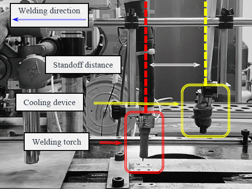
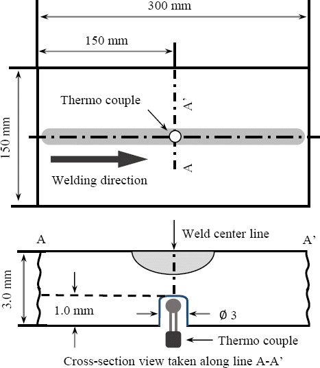
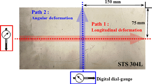
The material used for experiment and FE model was STS304L austenitic stainless steel, the chemical composition and mechanical properties of material are shown in Table 1. Fig. 1 shows trailing heat sink welding experiment set up, the water cooling device was attached to the GTAW weld torch with a following distance from 40 mm to 60 mm, and ordinary tap water was used as cooling media. The dimension of specimen were 300 mm in length, 150 mm in width and 3 mm in thickness. The bead-on-plate welding was implemented by using gas tungsten arc welding with or without a trailing heat sink using water cooling device. Table 2. shows the welding condition were a 90 A welding current, a welding speed of 3 mm/s, and the shielding gas was 100% Ar. The heat sink condition were a 0.2 ml/s flow rate, a heat sink radius of 7.5 mm, and the standoff distance were increased from 40 mm to 60 mm at intervals of 10 mm, the condition of standoff distance was selected considering the minimum safety distance to prevent water sprayed through the cooling device from flowing into the welds. The temperature profile during welding were measured by K-type thermo couple located under the weld lin at the center of the welded specimen, as shown in Fig. 2. Weld longitudinal deformation and angular deformation were measured at intervals of 25 mm using displacement dial gauge, as shown in Fig. 3.Table 1
Chemical compositions and mechanical properties of STS304L stainless steelChemical compositions (wt.%) C Mn Si P S Cr Ni N 0.08 2.0 0.75 0.045 0.030 20.0 10.5 0.10 Mechanical properties Tensile strength (MPa) Yield strength (MPa) Elongation (%) 515 210 40 Table 2
Conditions of welding and cooling device- 2.2 Finite Element Model
- 2.2 Finite Element Model
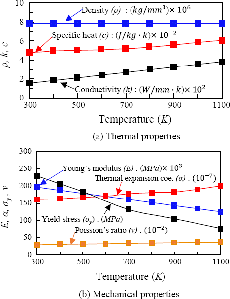
Numerical investigation was performed using the 3-D transient heat conduction and thermal elastic-plastic analysis. The dimension of FE model are the same as used in the experiment specimen. The elements used for the FE model were eight node, iso-parametric solid elements. The element division of welds was used fine mesh considering rapid temperature change occurring along the weld line, and it gets coarsened as it move away from welds10,11), the minimum size of the element has been 0.1 mm×0.5 mm×0.5 mm, as shown Fig. 4. The FE model contains of 138,467 nodes and 117,000 elements.The commonly-used meterial properties of STS304L stainless steel were used with consideration for temperature dependencies12-14), as shown in Fig. 5, respectively in the thermal conduction and thermal elastic-plastic analysis. As boundary conditions in the thermal conduction analysis, the heat transfer coefficient was set to 10×10-6 W/mm2 K and the initial temperature of the base material was set to 300 K considered as room temperature. The boundary condition for thermal elastic-plastic analysis was applied to prevent only rigid body motion to allow the free expansion of the which was same case in the experiment15).- 2.3 Heat Source and Heat Sink Model
- 2.3 Heat Source and Heat Sink Model
The moving heat source in this present study was expressed in the form of surface heat flux and energy distribution of the welding arc was assumed as Gaussian distribution following the equation as give belowwhere ηa is the arc efficiency, E is the arc voltage, I is the welding current, ro is the effective radius of the heat source, and r is the distance from the arc center16).The heat sink model was simulated the intense cooling effects due to presence of a heat sink, the heat sink was assumed to follow the welding arc with a standoff distance. The resulting energy density within the heat sink area was assumed to be uniform and was express aswhere ηh is the heat sink efficiency, Qv is the energy required by vaporization of water, Vf is the flow rate of the water, and b is the effective radius of the heat sink17). Through a series of numerical experiment, it was confirmed that the heat sink efficiency should be assumed by 50% to achieve satisfactory temperature prediction.The energy loss density qh due to presence of the trailing heat sink was considered as an equivalent convection loss effect with the following expressionwhere h is the equivalent convection coefficient, Ts is the surface temperature of model, Ta is the local ambient temperature within the heat sink area, which is assumed to be 293 K considering temperature of the water.

- 3. Analysis Results and Discussion
- 3. Analysis Results and Discussion
- 3.1 Temperature Distribution Characteristics
- 3.1 Temperature Distribution Characteristics
Fig. 6 shows the temperature distribution of weld line surface of welding with trailing heat sink and conventional welding when the welding start from 30 s. It can be found that the high temperature region was limited to the vicinity of heat source and a low temperature zone formed according to welding line. This low temperature zone provides a stretching effect on the weld metal under going a rapid cooling so that the weld metal shrinkage can be reduced18).Fig. 6
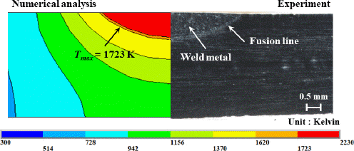
Temperature distribution of conventional welding and heat sink welding with various standoff distance Fig. 7 shows the cross-sectional view of the center of the weld metal obtained from the numerical analysis and experiment, the red region indicates temperatures above 1723 K. generally, the boundaries of the fusion zone obtained numerically had similar shapes in comparison with the experimental ones. Therefore, it was confirmed that the welding heat source applied to numerical analysis of FE model has a good agreement with those obtained experimentally.Fig. 8 shows the temperature profile of welds metal, heat-affected zone and base metal according to the standoff distance. Fig. 8(a) is shown the temperature profile of the weld metal. When the standoff distance of 40 mm, the temperature decreased by 192.4 K compared conventional welding at t = 23 s, in the standoff distance of 50 mm was reduced by 184.9 K at t = 26 s, in the case of standoff distance of 60 mm, the temperature reduced by 180.1 K at t = 29 s.
Fig. 8
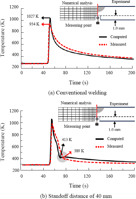
Comparison of temperature profile in conventional welding and heat sink welding with various standoff distance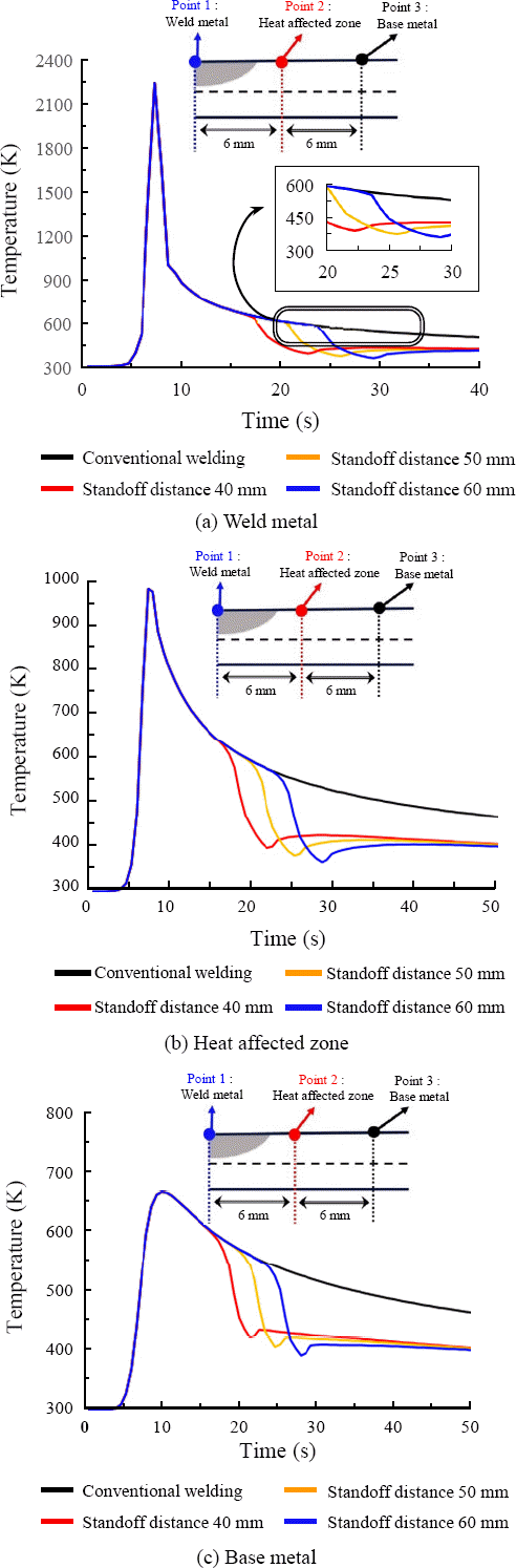 Fig. 8(b) is shown the temperature profile of heat-affected zone. When the standoff distance of 40 mm, the temperature decreased by 179.9 K compared conventional welding at t = 23 s, in the standoff distance of 50 mm was reduced by 173.4 K at t = 26 s, in the case of standoff distance of 60 mm, the temperature reduced by 169.9 K at t = 29 s. Fig. 8(c) is shown the temperature profile of base metal. When the standoff distance of 40 mm, the temperature decreased by 140.1 K compared conventional welding at t = 23 s, in the standoff distance of 50 mm was reduced by 136.7 K at t = 26 s, in the case of standoff distance of 60 mm, the temperature reduced by 135.4 K at t = 29 s.From the analysis results, the heat sink effect cannot decrease the maximum temperature but can increase the cooling rate. Furthermore, it was confirmed that the cooling rate was gradually increased as the standoff distance became shorter, and gradually decreased far away from the weld line. The measured temperature profile observed during conventional welding was shown in Fig. 9(a). Even though the experimental values of cooling rate in the thermal cycle does not correspond exactly to those computed value, the experimental values of peak temperature correspond roughly to those computed value. When standoff distance is 40 mm, as shown Fig. 9(b), the temperature during welding is cooled more rapidly compared to conventional welding, and temperature at measuring point rise again in the cooling stage, as shown in the shaded circle. This re-increase in temperature is also observed in computed thermal cycle.Thus, from the thermal conduction analysis results of the weld penetration and the thermal cycle generally agree with the experimental results. Therefore, it can be considered that the FE model of conventional welding and welding with trailing heat sink is constructed successfully.
- 3.2 Deformation Distribution Characteristics
- 3.2 Deformation Distribution Characteristics
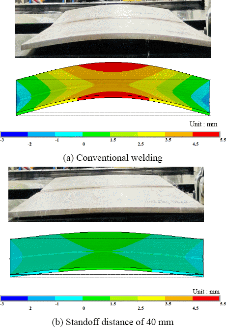
Fig. 10 shows the welding deformation distribution in a thickness direction of FE model according to standoff distance. The maximum displacement occurred at the left and right edge side of the center of the weld line in all standoff distance conditions, also it was confirmed that the displacement of thickness direction was significantly reduced as standoff distance shorter due to intensity of the heat sink effect.Fig. 10
Welding deformation distribution of conventional welding and heat sink welding with various standoff distance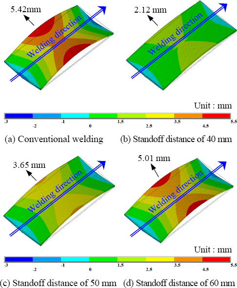 Fig. 11(a) shows the comparison of displacement of longitudinal direction according to standoff distances. The highest displacement was 5.50 mm, which was occurred in conventional welding, and the maximum displacement of trailing with a heat sink welding with standoff distances of 40 mm, 50 mm, and 60 mm was 2.22 mm, 3.78 mm, and 5.24 mm, respectively. From the result, it was confirm that the longitudinal deformation was reduced by up to 60% in heat sink welding with a standoff distance of 40 mm.
Fig. 11
Comparison of welding deformation in conventional welding and heat sink welding with various standoff distance Fig. 11(b) shows the comparison of displacement of transverse direction according to standoff distances. The highest displacement was 1.68 mm, which was occurred in conventional welding, and the maximum displacement of trailing with a heat sink welding with standoff distances of 40 mm, 50 mm, and 60 mm was 0.51 mm, 0.99 mm, and 1.45 mm, respectively. From the result, it was confirm that the angular deformation was reduced by up to 70% in heat sink welding with a standoff distance of 40 mm.Fig. 12, 13 shows the comparison of measured displacement for conventional welding and the trailing heat sink with standoff distance 40 mm. Although the measured value of displacement in the direction of longitudinal and transverse does not correspond exactly to those computed value, it was confirmed that there was a similar trend with experimental result in qualitative aspect.
Fig. 12
Comparison of welding deformation in conventional welding between experiment and numerical analysis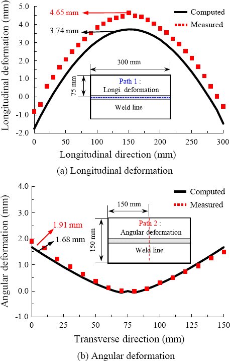
Fig. 13
Comparison of welding deformation in Heat sink welding with standoff distance of 40 mm between experiment and numerical analysis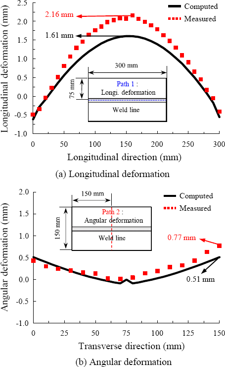 Fig. 14(a) shows the experimental validation of the trailing heat sink technique proposed, there were shown good agreement with the FE model. By welding with the trailing heat sink, longitudinal deformation and angular deformation was significantly reduced when compared to the conventional welding shown in Fig. 14(b).
- 4. Conclusion
- 4. Conclusion
1) From the thermal conduction analysis results, it was confirmed that the temperature in cooling stage of weld metal, heat-affected zone, and base metal were decreased by 192.4 K, 179.9 K, and 140.1 K in the heat sink welding with standoff distance of 40 mm compared to conventional welding.
2) From the thermal elastic-plastic analysis results, it was confirmed that the longitudinal deformation and angular deformation were approximately reduced by 60% and 70% in the heat sink welding with standoff distance of 40 mm compared to conventional welding.
3) From the above results, it could be inferred that the cooling effect was increased as the standoff distance became shorter, the intensity of cooling effect contributed to reduce of welding deformation.
In this study, thermal conduction and thermal elastic- plastic analysis was performed to investigate the reduction characteristics of welding deformation according to the standoff distances in heat sink welding process. Consequently, the following conclusions have been obtained.
- Acknowledgments
- Acknowledgments
This paper was supported by Korea Institute for Advancement of Technology (KIAT) grant funded by the Korea Government (MOTIE) (P0008425, The Com- petency Development Program for Industry Specialist)
- REFERENCES
- REFERENCES
References
1. H. S. Bang, Y. H. Cha, Y. K. Oh, C. S. Ro, and J. M. Kim. Numerical Analysis of Post Welding Heat Treatment Base on The Thermal Creep Elastic-Plastic Theory. J. Ocean Eng. Technol. 11 (1) (1997), 113–123 https://www.joet.org/journal/view.php?number=12122. D. Venkatkumar and D. Ravindran, Effect of Boundary Conditions on Residual Stresses and Distortion in 316 Stainless Steel Butt Welded Plate, High. Temp. Matls. Proc. 38(2019) 827–836. https://doi.org/10.1515/htmp-2019-0048
[Article]3. I. H. Kim, H. G. Kim, S. B. Shin, and D. H. Park, A Study on Welding Distortion of GTA Circular Type Lap Joint in STS304L Thin Plate, J. Weld. Join. 30(5) (2012) 57–63. https://doi.org/10.5781/KWJS.2012.30.5.57
[Article]4. M. He, J. Qi, Z. Zheng, F. Shi, and Y. Lei, (2020) Numerical simulation of nickel-based alloys'welding transient stress using various cooling techniques, High. Temp. Matls. Proc. 39(1) 633–644. https://doi.org/10.1515/htmp-2020-0067
[Article]5. Y. P. Yang and P. Dong, Buckling Distortions and Mitigation Techniques for Thin-Section Structures, J. Matls. Eng. Perf. 21(2) (2012) 153–160. https://doi.org/10.1007/s11665-011-9928-x
[Article]6. S. Okano, M. Mochizuki, M. Toyoda, and T. Ueyama, Effect of Weld Heat Input Conditions on Reduction of Angular Distortion by Heat-Sink Welding, Qtly. J. Japan Weld. Soc. 29(1) (2011) 55–60. https://doi.org/10.2207/qjjws.29.55
[Article]7. R. Holder, N. Larkin, H. Li, L. Kuzmikova, Z. Pan, and J. Norrish. Development of a DC-LSND welding process for GMAW on DH-36 Steel. 56th WTIA annual conference. Seattle, Australia: (2011), 1–13 https://ro.uow.edu.au/eispapers/580/8. S. Okano and M. Mochizuki, Experimental and Numerical Investigation of Trailing Heat Sink Effect on Weld Residual Stress and Dstortion of Austenitic Stainless Steel, ISIJ International. 56(4) (2016) 647–653. https://doi.org/10.2355/isijinternational.ISIJINT-2015-659
[Article]9. B. S. Go, K. H. Oh, S. I. Kwon, and H. S. Bang, Redu- ction Characteristics of Welding Deformation According to Cooling Distance in Heat Sink Welding, International Journal of Precision Engineering and Manufacturing. 23(11) (2022) 1229–1236.
[Article]10. J. M. Kim, C. S. Park, Y. P. Kim, and H. S. Bang. A Fundamental Study on Forecast of the Thin Plate Welding Deformation by Numerical Simulation. J. Korean Weld. Join. Soc. 21 (1) (2003), 93–98 https://www.e-jwj.org/journal/view.php?number=41805011. H. S. Bang and G. Y. Han. The Plane-Deformation Thermal Elasto-Plastic Analysis During Welding of Plate. J. Ocean Eng. Technol. 8 (1) (1994), 33–40 https://koreascience.kr/article/JAKO199411920577024.page12. R. M. Farias, P. R. Teixeira, and D. B. Araújo, Thermo- mechanical analysis of the MIG/ MAG multi-pass welding process on AISI 304L stainless steel plates, J. Brazilian Soc. of Mech. Sci. Eng. 39 (2017) 1245–1258. https://doi.org/10.1007/s40430-016-0574-y
[Article]13. S. A. A. Mousavi, . S. A, and R. Miresmaeili, Experimental and numerical analyses of residual stress distributions in TIG welding process for 304L stainless steel, J. Matls. Proc. Technol. 208(1-3) (2008) 383–394. https://doi.org/10.1016/j.jmatprotec.2008.01.015
[Article]14. R. Bhadra, P. Pankaj, P. Biswas, and U. S. Dixit, Thermo- Mechanical Analysis of CO2 Laser Butt Welding on AISI 304 Steel Thin Plates, Intl. J. Steel. Str. 19(1) (2019) 14–27. http://doi.org/10.1007/s13296-018-0085-z
[Article]15. H. Huang, X. Yin, Z. Feng, and N. Ma, Finite element analysis and in-situ measurement of out-of-plane distortion in thin plate TIG welding, Materials. 12(1) (2019) 141https://doi.org/10.3390/ma12010141
[Article] [PubMed] [PMC]16. E. Friedman, Thermomechanical Analysis of the Welding Process Using the Finite Element Method, J. Press. Ves. Technol. 97(3) (1975) 206–213. https://doi.org/10.1115/1.3454296
[Article]17. Y. P. Yang, P. Dong, J. Zhang, and X. Tian, A Hot- Cracking Mitigation Technique for Welding High- Strength Aluminum Alloy, Welding Journal. New York: 79(1) (2000) 9-s18. S. Okano, M. Mochizuki, M. Toyoda, and T. Ueyama, Effect of welding conditions on reduction in angular distortion by welding with trailing heat sink Sci, Technol. Weld. Join. 17(4) (2012) 264–268. https://doi.org/10.1179/1362171811Y.0000000103
[Article]